AMELH6030S-1R2MT: Complete Datasheet & Sourcing Guide
The AMELH6030S-1R2MT is rated for a 19 A saturation current and a 40 MHz self-resonant frequency—specs that make it a top choice for high-current SMD power supplies. Point: this guide distills published datasheet values into design-ready guidance. Evidence: the component family is a flat-wire, hot‑pressed molded power inductor engineered for low DCR and high Isat. Explanation: readers will get a concise datasheet breakdown, practical layout and test recommendations, and clear steps for sourcing in the US market; the word "datasheet" is used here to emphasize the importance of referring to manufacturer tables for exact limits and test conditions.
Point: the purpose is actionable: pick the right inductor, validate thermal/EMI behavior, and buy authentic parts. Evidence: this document translates electrical and mechanical tables into design checks and test procedures. Explanation: follow-through checks (DC R, inductance under DC bias, temperature-rise) are presented in step sequence so engineering teams can qualify AMELH6030S-1R2MT for dense DC‑DC converters with predictable margins.
1 — Product background & key specs (Background)
1.1 Overview & typical applications
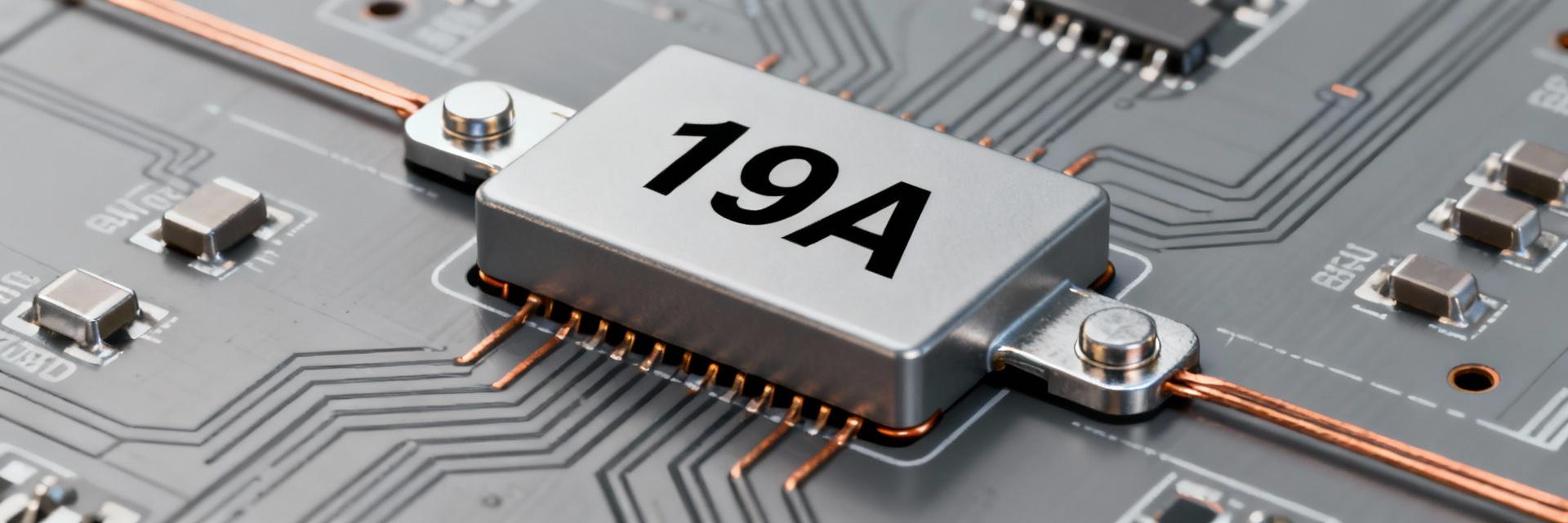
Point: the AMELH6030S-1R2MT family is a flat-wire, hot‑pressed molded power inductor optimized for high-current SMD applications. Evidence: this family is commonly deployed in buck converters, voltage regulator modules (VRMs), automotive power rails, and industrial DC‑DC supplies where space and thermal handling are constrained. Explanation: the flat‑wire geometry increases cross‑sectional copper area and reduces DCR, improving conduction efficiency and thermal spreading; combined with a molded package it tolerates automated assembly and provides predictable magnetic shielding for high-density boards.
1.2 Mechanical dimensions & package information
Point: mechanical footprint and handling details determine assembly yield and thermal behavior. Evidence: the AMELH6030S-1R2MT uses a compact SMD footprint with a low profile suited to 1.2 µH cores; manufacturers publish recommended land patterns and tape‑and‑reel packaging for automatic placement. Explanation: follow the datasheet’s recommended land pattern to avoid reflow tombstoning and to ensure adequate thermal copper area; treat reels per MSL guidance (bake and reflow limits) and confirm tape orientation with pick-and-place before production run.
1.3 High-level electrical highlights
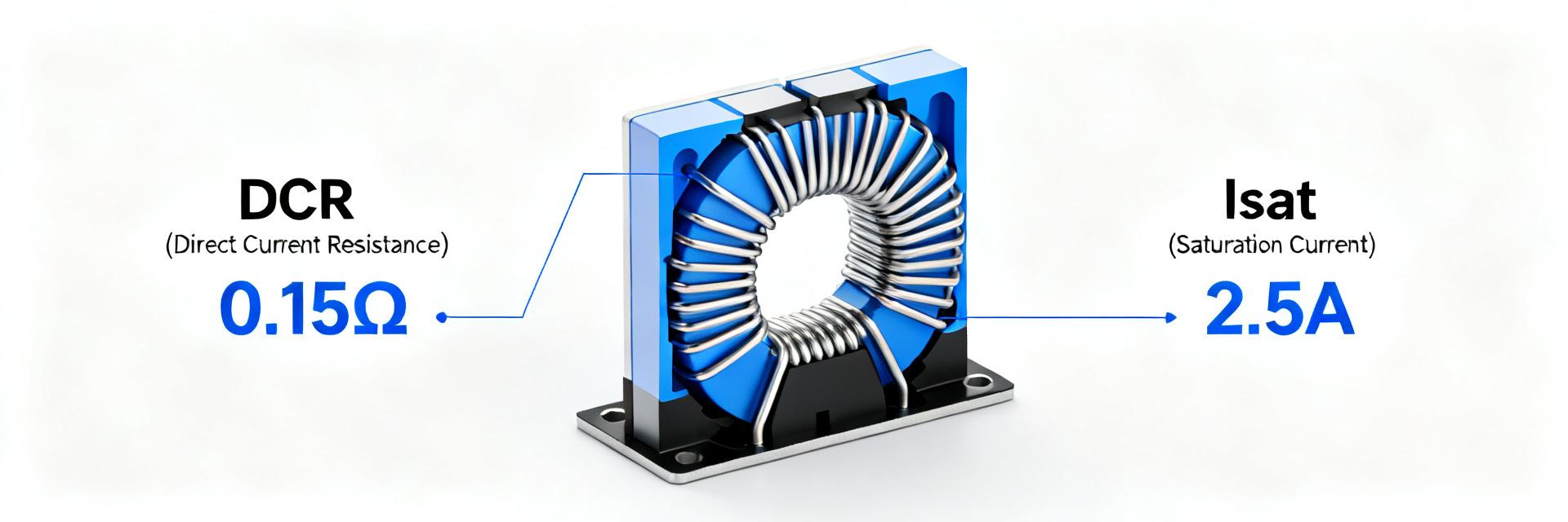
Point: key electrical specs are the starting point for selection. Evidence: nominal inductance is 1.2 µH with standard tolerance class, Isat (saturation current) specified at 19 A, and a self‑resonant frequency around 40 MHz; the device operates across a wide temperature window (typically −40 to +125 °C). Explanation: expect low single‑digit to low double‑digit milliohm DCR values in this family—important for conduction loss calculations—and always consult the full datasheet tables for part‑number‑specific DCR and rated current values.
2 — Datasheet deep-dive: how to read the numbers (Data analysis)
2.1 Electrical characteristic interpretation
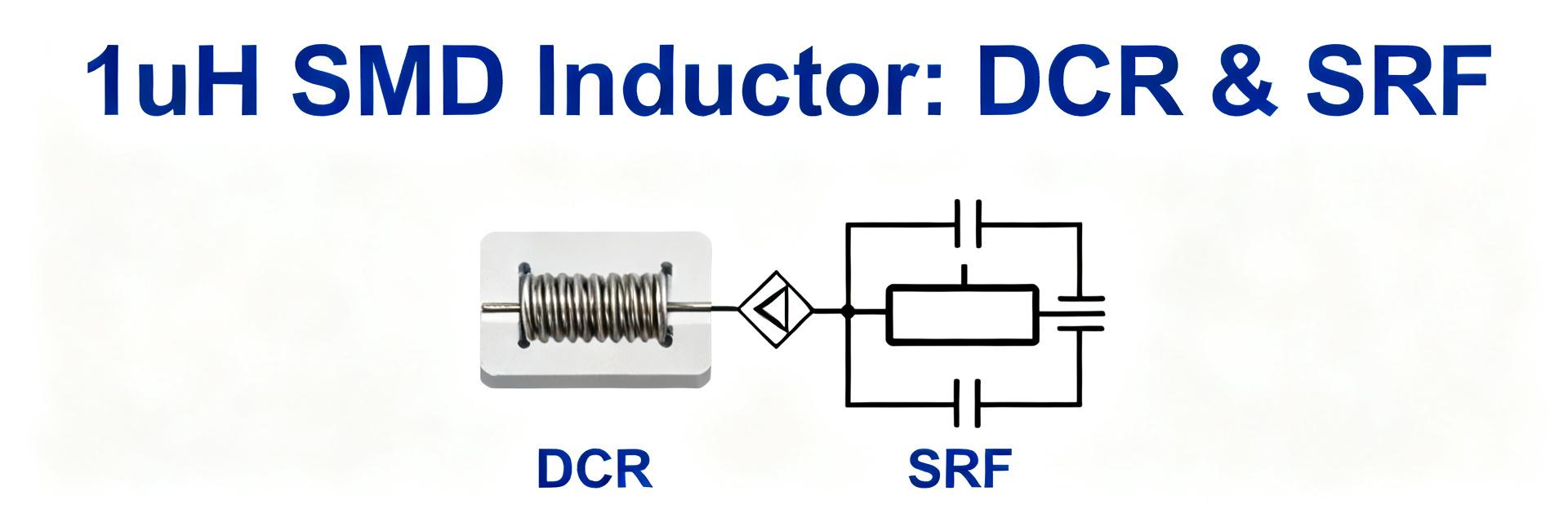
Point: interpreting inductance, DCR, DC‑bias behavior and saturation ratings is essential to match an inductor to a converter’s ripple and peak currents. Evidence: datasheet tables typically list inductance at 100 kHz/0 V bias, DCR (ohmic) measured per a defined method, Isat where L falls by a specified percent, and rated current based on temperature rise limits. Explanation: use inductance vs. frequency curves to verify that the inductor maintains sufficient reactance at the switching frequency; treat DCR as a loss term in the I²R loss budget; use Isat to prevent core saturation during peak events and use rated current to estimate steady‑state temperature rise. When documenting, cite the exact rows in the datasheet labeled "Electrical Characteristics" and "DC Resistance" for reproducible selection.
2.2 Thermal, environmental & reliability specs
Point: thermal derating and environmental limits determine real‑world performance. Evidence: datasheets provide temperature coefficients, operating temp ranges (commonly −40 to +125 °C), temperature‑rise at rated current, MSL level, and RoHS/REACH statements. Explanation: derate rated current when ambient temperature rises or airflow is restricted—apply the datasheet’s temperature‑rise curves or use a conservative percentage derating per 10 °C above nominal; follow MSL handling instructions (bake if required) and retain supplier attestations for compliance and traceability.
2.3 Test conditions & measurement caveats
Point: reported values depend on test fixturing and equipment. Evidence: manufacturers measure L and DCR under controlled fixtures, specific frequencies, and without nearby conductive planes that alter inductance. Explanation: replicate the datasheet test conditions as closely as possible when measuring—use a short Kelvin jig for DCR, measure inductance with a calibrated LCR at the same frequency and bias, and be aware that PCBs with large ground pours or adjacent components will shift L and SRF; document differences between board‑level and standalone measurements.
3 — Design & integration best practices (Method guide)
3.1 PCB footprint, placement & thermal management
Point: layout choices materially affect DCR heating and EMI. Evidence: high current loops produce I²R losses and radiated fields; datasheet rated current assumes specified ambient and airflow. Explanation: place the inductor close to the switching node, minimize input/output loop area, and provide wide copper pours on input and output nets for heat spreading; add thermal vias beneath adjacent MOSFETs or sense resistors as needed. Keep sensitive sense traces and compensation components away from the switching node to avoid interference, and verify that copper pour clearance does not degrade inductance unacceptably.
3.2 EMI, filtering and snubber considerations
Point: the inductor’s characteristics influence both conducted and radiated emissions and the need for additional filtering. Evidence: SRF and winding geometry determine how the part behaves at switching harmonics; low DCR parts may still allow high di/dt to create EMI. Explanation: if conducted emissions appear near switching harmonics, add an RC snubber or a small series ferrite on the switch node to damp high‑frequency ringing; consider common‑mode chokes or additional LC filters on inputs/outputs where regulatory limits require. Evaluate EMI in the intended enclosure as layout and shielding change results.
3.3 Verification & test procedures
Point: follow a reproducible verification sequence to qualify the part in your design. Evidence: practical tests include DC resistance check, inductance under DC bias, temperature‑rise at rated current, and in‑circuit efficiency/transient response testing. Explanation: measure DC R with a Kelvin 4‑wire method and compare to datasheet tolerance; apply DC bias equal to expected peak current and measure L drop to confirm margin from saturation; run a thermal soak at rated current while monitoring temperature rise with thermocouples attached to the component case; validate converter efficiency and transient load‑step response on the assembled board and use those results to iterate layout or part choice.
4 — Real-world case study: 12 V → 1.2 V buck converter using AMELH6030S-1R2MT (Case study)
4.1 Circuit context & part selection rationale
Point: selecting a 1.2 µH, 19 A‑Isat inductor for a 12 V → 1.2 V buck balances ripple, size and saturation margin. Evidence: target converter switching frequency and expected peak currents (e.g., several amps of ripple and >10 A steady load) inform inductance and Isat choice. Explanation: for a 500 kHz switching frequency, 1.2 µH yields a tradeoff between acceptable ripple current and physical size; choosing the AMELH6030S-1R2MT provides a safety margin on Isat so that transient peaks do not collapse inductance, while its low DCR keeps conduction losses manageable—verify with the converter’s calculated peak current and the datasheet’s bias curves.
4.2 Measured performance & thermal results
Point: reportable metrics include efficiency across load, output ripple, inductor temperature rise, and any saturation signatures. Evidence: bench results typically show efficiency degradation attributable to I²R loss and switching loss; temperature rise is measured from ambient to winding or case. Explanation: measure efficiency at light, mid, and full load; quantify output ripple with a high‑bandwidth probe, and watch for flattening or nonlinearity in inductance vs. current as an indicator of approaching saturation. If temperature rise exceeds datasheet expectations, increase copper pour, add airflow, or select a higher rated part.
4.3 Lessons learned & failure modes
Point: common pitfalls include undervaluing DC bias effects and inadequate cooling. Evidence: teams often see higher than expected ripple or thermal issues when relying only on nominal inductance values. Explanation: mitigate by measuring inductance under expected DC bias before finalizing the BOM, provide margin against Isat for worst‑case transients, and plan thermal management early—insufficient spacing, or placing heat‑dissipating MOSFETs too close, can elevate inductor temperature and reduce lifetime.
5 — Sourcing & procurement checklist for US buyers (Action advice / Sourcing)
5.1 Authorized distributors & stock-check tips
Point: source only from authorized distributors to avoid quality and traceability risks. Evidence: primary channels in the US include well‑known authorized distributors who list manufacturer part numbers and traceability. Explanation: when searching for AMELH6030S-1R2MT, verify distributor authorization on the manufacturer’s distributor list, confirm part numbers and reel sizes, and query for packing details; use exact family codes and search synonyms to ensure you find correct reel quantities and packaging options—document stock dates and lot numbers for future audits.
5.2 Pricing, lead times, MOQ and counterfeit avoidance
Point: pricing and lead times vary with demand, lot, and reel quantities; counterfeit risk rises with non‑authorized channels. Evidence: typical procurement variables include unit vs reel pricing, MOQ, and rush fees; counterfeit indicators include unusually low price, inconsistent packaging, or missing traceability. Explanation: ask suppliers for COA (Certificate of Analysis), lot traceability, and clear packaging photos; prefer reel purchases for production and request small sample reels for initial qualification; if lead times extend, discuss allocation or last‑time buy alternatives with authorized channels to maintain supply continuity.
5.3 Cross-references and alternatives
Point: have qualified alternates to avoid single‑source risk. Evidence: equivalent parts are evaluated by matching inductance, DCR, Isat, SRF and package size. Explanation: create a short checklist for alternates—nominal L and tolerance, DCR ceiling, saturation current at defined % L drop, rated current (temperature rise), and physical footprint—run the same verification tests on alternates before substituting in production to avoid surprises.
Summary
- AMELH6030S-1R2MT is a high-current molded flat‑wire power inductor suitable for dense DC‑DC designs; consult datasheet tables to match DCR and Isat to load currents and ripple requirements.
- Use the datasheet electrical and thermal tables to derate for ambient temperature and airflow; validate L under DC bias and run a temperature‑rise test at rated current before qualification.
- Follow PCB layout best practices—short loops, wide copper pours, and thermal vias—and add filtering or snubbers if EMI measurements exceed limits.
- For sourcing, prefer authorized distributors, request COA and lot traceability, and qualify alternates against an explicit checklist to mitigate supply risk.
FAQ
What are the key datasheet rows to check when selecting AMELH6030S-1R2MT?
Check the electrical characteristics table (inductance at specified test frequency), the DC resistance table (milliohms and tolerance), the saturation current row (Isat definition and percent L drop), and the temperature‑rise/rated current rows. Also review mechanical drawings for land pattern and tape‑and‑reel packaging, plus MSL and operating temperature limits to align handling and qualification steps. These rows let you calculate I²R losses, derate for temperature, and confirm footprint compatibility.
How should I test AMELH6030S-1R2MT to verify thermal performance?
Perform a temperature‑rise test by mounting the part on the target PCB, applying the expected steady current, and logging temperature with a thermocouple attached to the inductor casing and nearby PCB. Compare the measured rise to the datasheet’s rated‑current temperature‑rise value; if higher, improve copper pours or airflow. Also run a soak test at elevated ambient to verify long‑term stability, and measure inductance under the same DC bias to ensure saturation margin remains acceptable.
What are the best procurement practices for sourcing AMELH6030S-1R2MT in the US?
Buy from authorized distributors and request COA and lot traceability; prefer reel purchases for production and save sample reels for qualification. Verify packaging photos and reel labeling, watch for unusually low prices or inconsistent packaging as red flags, and document contact and warranty terms. If lead times are long, plan alternates and ask suppliers about allocation or last‑time buy options to protect production schedules.