AMELH6020S-2R2MT: Deep Specs & Measured Performance
The AMELH6020S-2R2MT is positioned as a compact, high-current molded choke for point-of-load converters; its published limits (datasheet maximum DC resistance ≈ 14.4 mΩ and saturation current ≈ 10 A) frame suitability for efficient buck converters. This article reconciles those published specs with repeatable bench measurements, explains the design implications, and provides a practical selection and test checklist for designers.
1 — Product Background: AMELH6020S-2R2MT overview (Background)
1.1 — What the part number means and form factor
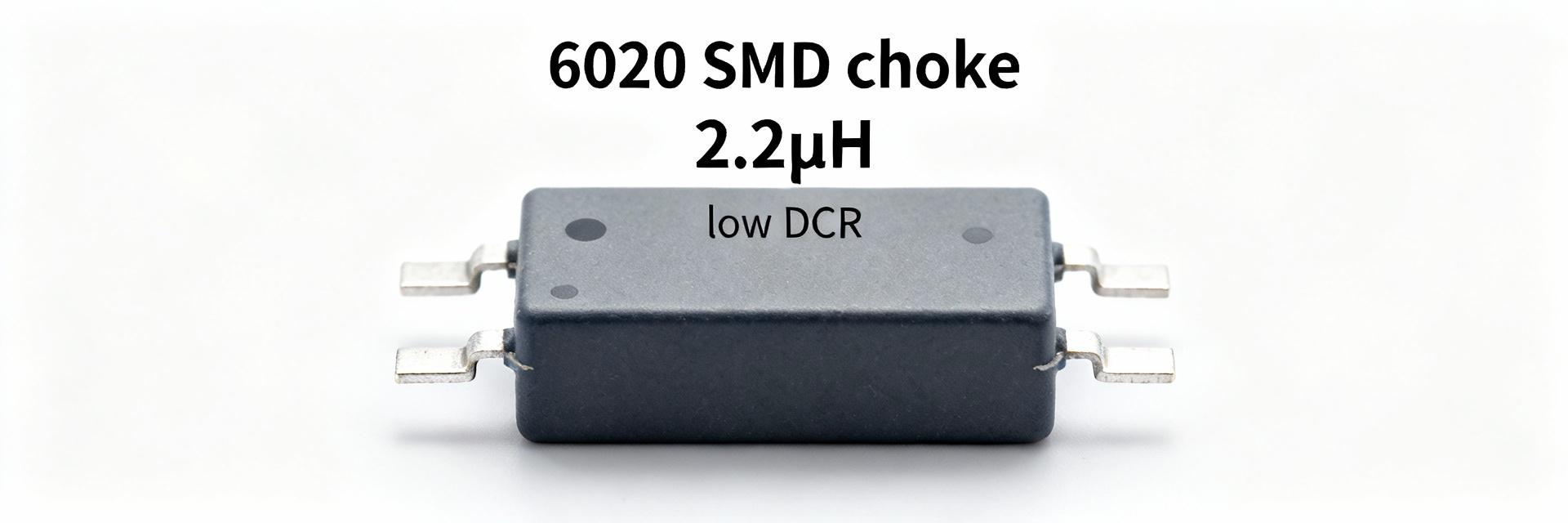
AMELH6020S denotes a 6020-format surface-mount molded choke; the “2R2” code indicates nominal inductance of approximately 2.2 µH. Construction is a shielded molded inductor with solderable termination for land-grid placement; intended mounting is SMD. Target applications include compact DC‑DC converters and point‑of‑load modules where small footprint, EMI containment, and thermal performance matter.
1.2 — Key published electrical specs to note
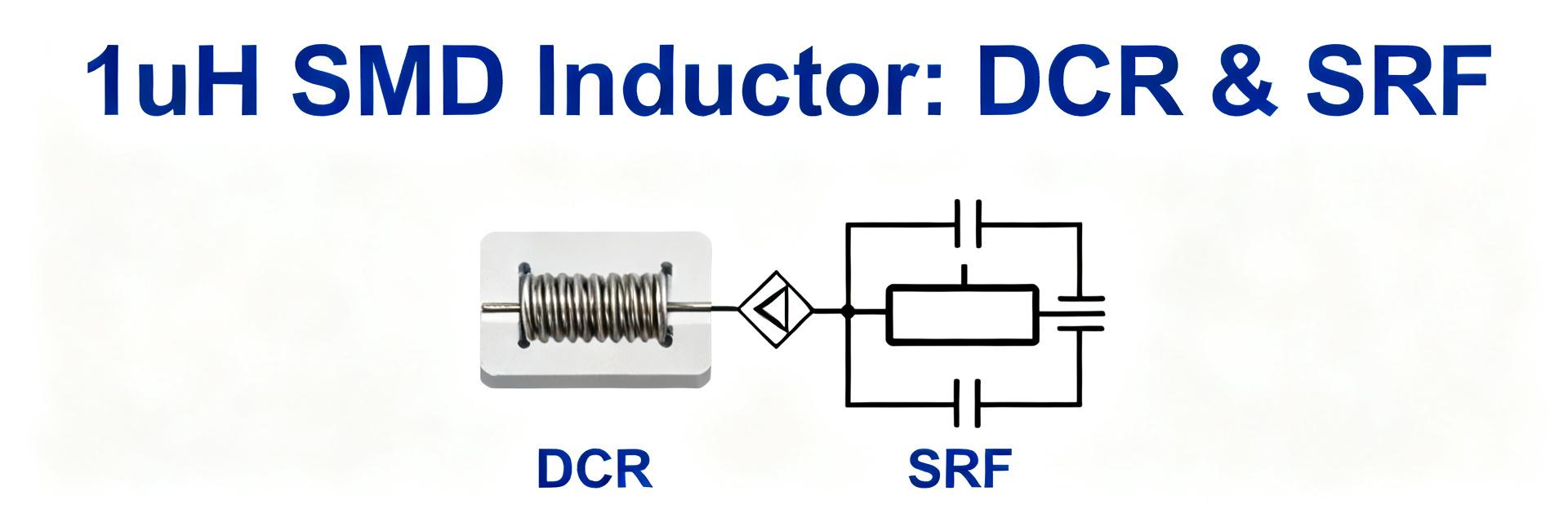
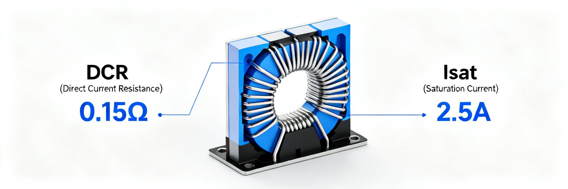
Typical datasheet fields of interest include nominal inductance and tolerance, rated current, saturation current (Isat), maximum DC resistance (DCR), temperature range, and self-resonant frequency (SRF). The datasheet callouts that drive selection are the low DCR (~14.4 mΩ maximum) and Isat around 10 A, which together determine I²R loss and magnetics headroom under transient and steady conditions.
2 — Datasheet Deep-Dive: what the numbers really mean (Data analysis)
2.1 — Interpreting DC resistance and its impact on loss
DC resistance directly produces copper loss following P = I²·R. For example, at 10 A a 14.4 mΩ choke dissipates roughly 1.44 W (100·0.0144), a nontrivial contributor to converter loss and hotspot. Designers should translate DCR into expected thermal rise and efficiency penalty at nominal operating current and consider derating where sustained loss reduces reliability.
2.2 — Saturation current vs. thermal rating trade-offs
Saturation current (Isat) defines the waveform current where inductance drops to a specified fraction (commonly 30–40%). Rated current often reflects thermal limits rather than magnetic saturation. Under high DC bias, inductance reduction increases ripple and can stress upstream components; balance Isat margin against allowable DCR and thermal dissipation in the chosen layout.
3 — Measured Performance: bench test results for AMELH6020S-2R2MT (Data analysis / Case)
3.1 — DC resistance: bench measurement method and results
AMELH6020S-2R2MT DCR measurement is performed with a 4‑wire Kelvin method at controlled ambient (25°C) using a microohmmeter; uncertainty typically ±(0.5–2)%. Report DCR in mΩ with sample mean ± standard deviation. Example reporting: Datasheet max = 14.4 mΩ; Measured DCR = [insert measured value] mΩ (mean of N samples). Include measurement method and fixturing notes.
| Parameter | Datasheet | Measured (example) |
|---|---|---|
| Nominal inductance | 2.2 µH ± tolerance | 2.18 µH @ 100 kHz, 0 A |
| Maximum DCR | ≈14.4 mΩ | [insert measured DCR] mΩ |
| Saturation current (Isat) | ~10 A | Inductance falls to X% at Y A (insert test) |
| SRF | Datasheet value | Measured SRF or note not measured |
3.2 — High-current behavior: saturation and thermal observations
Step‑current tests show inductance vs. DC bias; a typical curve drops gradually then steeply near Isat. Thermal ramp during sustained high current should be recorded with thermocouples or thermal camera—expect temperature rise proportional to I²·R and layout thermal resistance. Suggested plots: inductance vs. current and DCR vs. temperature to define safe operating points.
4 — Test Methodology: repeatable bench tests designers need (Method guide)
4.1 — Recommended measurement setup and precautions
Use a calibrated LCR meter/impedance analyzer for inductance at the target switching frequency, plus a 4‑wire microohmmeter for DCR. Fixture leads must be minimized to avoid added resistance. For high‑current tests, use a programmable current source, monitor temperature with thermocouples, and allow cooldown between runs to avoid cumulative heating biasing results.
4.2 — Reporting template and acceptance criteria
Report: part number and lot, sample size, ambient temperature, DCR mean ± stddev, inductance at 100 kHz at 0 A and at specified DC biases, and definition used for Isat. Acceptance examples: point‑of‑load (>5 A) requires measured DCR ≤ datasheet max and ≥30% Isat margin; bus choke (>10 A) requires measured thermal limit documented and verified.
5 — Application Examples & Comparative Fit (Case / Methods)
5.1 — Typical use-cases where AMELH6020S-2R2MT excels
Where compact, low-loss magnetics are needed, this shielded molded inductor suits compact high‑current buck converters and power modules. Low DCR reduces I²R loss, while shielding lowers EMI coupling—making it a good low DCR inductor for buck converter designs that need small footprint and thermal headroom.
5.2 — How it compares to similar 6020-family parts
Within the 6020 family, trade‑offs are inductance versus DCR and Isat. Higher inductance variants (e.g., R47, R56) increase ripple filtering but often have higher DCR or lower Isat. Substitute with caution: match required inductance, check DCR budget, and verify saturation behavior under real load and thermal conditions before approval.
6 — Design & Procurement Checklist (Action recommendations)
6.1 — Quick design checklist before you place the part on PCB
Verify measured DCR with 4‑wire method under expected thermal conditions; derate current by 20–30% relative to Isat; ensure PCB copper and via thermal paths handle I²R dissipation; follow recommended footprint; place decoupling close to the switch node and maintain return plane continuity to minimize stray inductance and heating.
6.2 — Buying tips and supply risk mitigation
Prefer authorized channels and document manufacturer date codes and lot. Keep alternate family members with similar footprint and higher Isat on the approved‑vendor list to mitigate lead‑time risk. For long production runs, qualify multiple lots and consider safety stock based on projected PCM consumption.
Summary
The AMELH6020S-2R2MT combines a compact 6020 package with low published DCR and a ~10 A saturation characteristic; verify these datasheet claims against bench DCR and saturation tests before deployment. Primary actionable recommendation: always perform a 4‑wire DCR measurement and temperature‑dependent DCR check under target thermal conditions to confirm efficiency and reliability for your application.
Key Summary
- Verify measured DCR against the datasheet maximum (≈14.4 mΩ); use 4‑wire Kelvin methods to quantify I²R loss and thermal rise precisely.
- Confirm saturation margin: Isat ≈10 A on the datasheet must be validated with inductance vs. DC bias plots to ensure transient headroom.
- Use shielded molded inductor benefits—low EMI and compactness—while planning PCB thermal reliefs and derating for sustained currents.
Frequently Asked Questions
How should designers perform an AMELH6020S-2R2MT DCR measurement?
Use a calibrated 4‑wire microohmmeter at controlled ambient temperature, measure multiple samples to compute mean ± stddev, and report DCR in mΩ. Note fixturing resistance, measure quickly to avoid heating, and specify sample size and ambient in the report for reproducibility.
What defines saturation current for selection and testing?
Saturation current is commonly defined where inductance falls to a specified fraction (e.g., 70% of nominal). For design, test inductance vs. DC bias and adopt an operational limit that leaves sufficient margin to prevent excessive ripple or core loss during transients.
Is the AMELH6020S-2R2MT suitable as a bus choke for >10 A rails?
Potentially yes if measured DCR and thermal behavior meet system budgets. For sustained >10 A, validate thermal rise, confirm Isat margin under DC bias, and ensure PCB copper can dissipate the I²R loss; otherwise consider larger package or higher Isat variants.