
The rise in switching-power density and mainstream multi-MHz converters has driven demand for compact, high-current magnetic components. Engineers increasingly reach for a robust power inductor to balance conduction loss, saturation, and thermal limits. AMELH6060S-1.0μH represents a typical 6.8 × 6.6 × 6.0 mm solution whose trade-offs illustrate that balance in practice.
This article frames the AMELH6060S-1.0μH by nominal inductance (1.0μH), package footprint (6.8 × 6.6 × 6.0 mm as shown in the datasheet), and the primary design trade-offs engineers evaluate: DCR versus Isat versus thermal rise. It provides actionable insights into datasheet curves and concrete test/layout steps for modern application designs.
Power Inductor Fundamentals & Key Specs
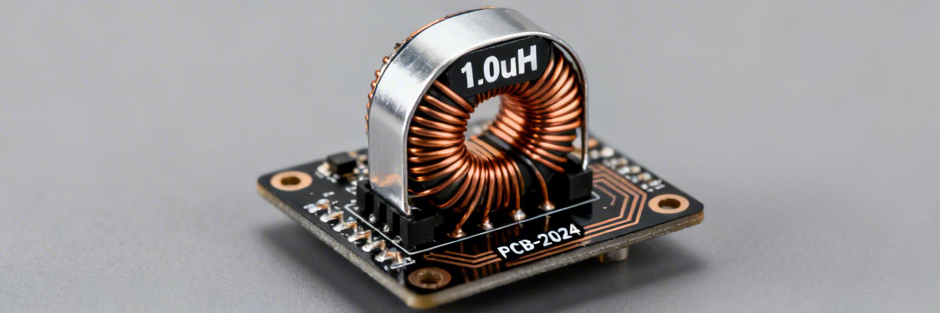
What “Power Inductor” Means for Switching Supplies
Core Concept: In buck/boost converters and EMI filters, the power inductor stores energy and sets ripple; current handling defines usable inductance under load. Evidence: Datasheet curves for L(f) and L vs. I reveal retained inductance across operating currents. Application: Selectors prioritize inductance value, saturation current (Isat), rated current/Irms, and DCR to meet efficiency and thermal goals in a given switching topology.
- • Essential specs: Nominal L and tolerance, DCR (typical/maximum), Isat and Irms, L vs. I curve, L(f)/Z(f) or SRF, temperature range, mounting style.
- • Practical note: Prioritize Isat and Irms with headroom for duty-cycle and transient events; DCR drives efficiency at continuous load.
Quick-Spec Reference Table
| Parameter | Value / Note |
|---|---|
| Nominal Inductance | 1.0μH |
| Tolerance | (Refer to exact datasheet table/figure) |
| Package Dimensions | 6.8 × 6.6 × 6.0 mm |
| DCR (typ / max) | (Refer to electrical values table) |
| Saturation Current (Isat) | (Cite figure number for Isat) |
| Rated Current / Irms | (Refer to thermal current specs) |
Electrical Performance Deep-Dive
Inductance vs. Frequency and Impedance Behavior
L(f) and Z(f) curves show when the part behaves inductively and where SRF (Self-Resonant Frequency) causes impedance roll-off. For a 1.0μH device, target switching frequencies well below SRF—commonly a decade lower—to ensure predictable inductance at the switching fundamental and its lower harmonics.
DC-bias and Saturation: L vs. I Curves
DC bias reduces effective inductance; Isat is defined at a specified percentage drop in L. A common derating rule is to design so operating current keeps >70–80% of nominal L. If L drops more, expect greater ripple or choose a higher-Isat part or parallel devices.
Thermal, Losses & Reliability
DCR, I2R Losses, and Temperature Rise
Conduction loss dominates at high DC loads. Loss is calculated as: Loss = Irms2 × DCR. For example, if DCR = 10 mΩ and Irms = 8 A, loss = 82 × 0.01 = 0.64 W.
Relative Power Loss Visualization (Sample at 10mΩ)
Reliability and Manufacturing
Solder and thermal limits constrain assembly. For high-current rails, confirm the recommended solder profile and board mounting pattern to avoid tombstoning or cracked terminations under thermal cycling. Always check max operating temperature and mechanical packaging (reel) specs before full-scale production.
Design Selection & Integration Guide
Selection Checklist
1) Compute required L from fsw and desired ripple current (ΔI = Vout × (1−D) / (L × fsw)); 2) Choose Isat/Irms with 20–30% headroom; 3) Check DCR meets efficiency targets; 4) Confirm thermal rise via empirical testing.
PCB Layout & EMI Tips
Place the inductor close to the switching node to minimize loop area. Use short, wide traces and place ground vias under the return plane. Add thermal vias if the inductor requires board heat-sinking. Follow recommended pad geometry and avoid flexing the board during reflow to maintain component integrity.
Bench Test Case Study: 10 A Buck Converter
Test Setup
Use a scope with differential probes, LCR meter, DC load, and thermal camera. Capture L under DC bias, DCR, and inductor surface temperature over time. Ensure proper probe grounding to avoid false ripple readings.
Interpreting Results
Compare measured ripple and temperature to design specs. If limits are exceeded, consider a lower-DCR variant, parallel inductors, or increased airflow. If L retention is insufficient, upgrade to a higher-Isat part.


