
AMELH6060S-R68MT Datasheet Deep Dive: Key Specs & Uses
These specifications are critical because inductance determines current ripple, current ratings limit throughput before saturation or excessive heating, and DCR (DC Resistance) dominates conduction loss—all decisive factors for power converter selection based on the component's datasheet.
Product Background & Reading the Datasheet
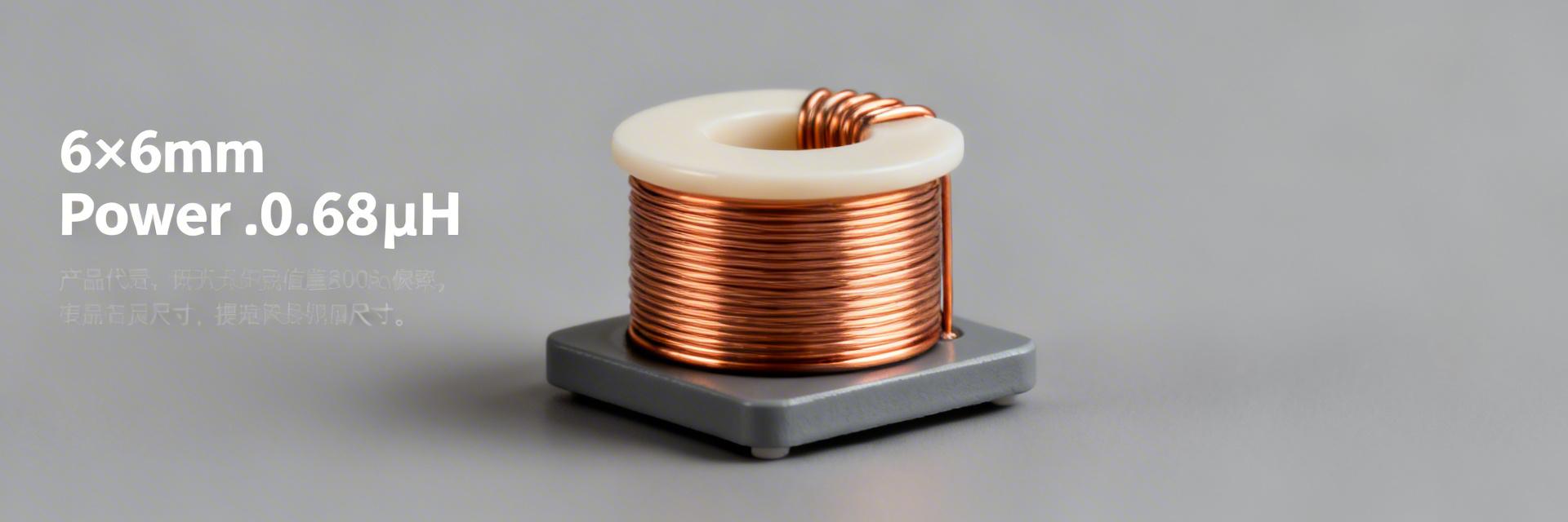
Part-Number Decoding & Package Outline
The part number encodes inductance, tolerance, and package family. For instance, the "R68" token denotes 0.68 μH nominal; suffixes often indicate tape-and-reel packaging or material processes. Designers should decode these fields to map value → tolerance → packaging, and inspect the mechanical drawing for footprint and mounting style (surface-mount, flat-wire molded).
| Field | Meaning |
|---|---|
| AMELH6060S | Family / package 6.0×6.0 mm flat-wire molded inductor |
| R68 | Nominal inductance: 0.68 μH |
| MT | Packaging / tolerance code (refer to datasheet specifics) |
Datasheet Structure: Critical Specs & Test Conditions
Key sections include electrical characteristics, absolute maximums, and mechanical/thermal test conditions. Note that inductance test frequency, DCR measurement methods, and DC-bias notes are typically in footnotes. It is essential to extract eight data points: L, tolerance, test frequency, DCR, Irms, Isat, temperature rating, and mechanical outline to evaluate component suitability.
Electrical Specs Explained
Core Electrical Parameters
Inductance (L), DCR, Isat, and Irms are the primary factors influencing converter performance. L sets current ripple; DCR causes I²R loss; Isat is the point where inductance collapses under DC bias, while Irms limits temperature rise under continuous load.
*Visualization based on nominal AMELH6060S series performance ratios.
Practical Calculations & Examples
Efficiency Example: For a buck converter switching 12V → 5V at 500 kHz:
- • Current Ripple: ΔI ≈ (Vin–Vout) / (L · fSW)
- • Conduction Loss: P = I²rms · DCR → 8² · 0.01 = 0.64 W
Thermal, Reliability & Mechanical Considerations
Thermal Behavior & Derating
Temperature determines safe continuous current. Datasheets typically provide Tmax and temperature-rise at Irms. Pro Tip: If ambient exceeds 50°C, apply a conservative rule: reduce Irms by 20–30%. Always confirm with thermal imaging under realistic PCB conditions.
PCB Footprint & Mounting
Follow mechanical drawing notes for pad geometry and solder fillet recommendations. Validate reflow profile compatibility and conduct mechanical vibration tests, especially for heavy molded power inductors on high-current boards.
Design Integration Checklist
Key Summary
- ✓ The datasheet shows 0.68 μH with distinct Irms vs Isat behavior; validate L under DC bias and use DCR for thermal planning.
- ✓ Follow mechanical drawing pad recommendations and derate continuous current by 20–30% for high ambient temperatures.
- ✓ Use bench tests (Kelvin DCR, thermal imaging, EMI scans) to confirm the part meets ripple, loss, and reliability targets.
Frequently Asked Questions


