
Key Takeaways (GEO Summary)
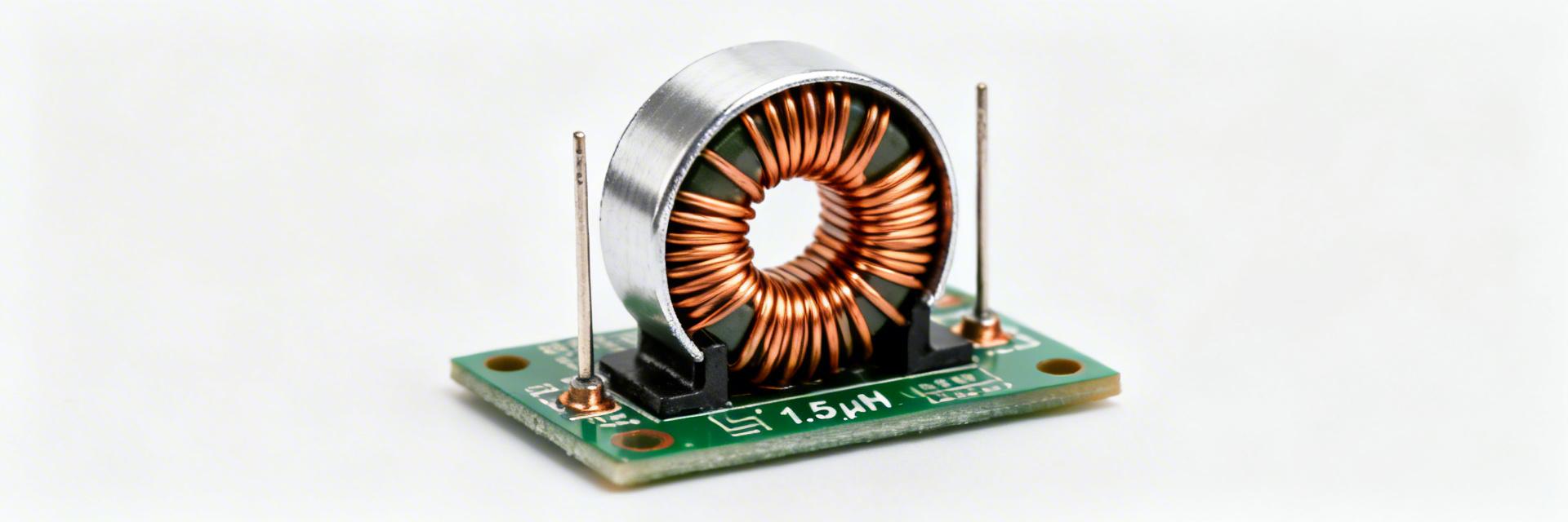
- High-Efficiency 1.5µH Inductor: Optimized for Point-of-Load (PoL) converters to minimize I²R losses.
- Superior Thermal Stability: Molded shielding design supports high-density PCB layouts with minimal EMI interference.
- Saturation Advantage: Maintains stable inductance under high DC bias, preventing regulator instability during peak loads.
- Compact 5030 Footprint: Ideal for space-constrained industrial and consumer electronics requiring robust power filtering.
Precise inductor specs drive losses, thermal rise, and usable switching frequency in power designs. Small shifts in DCR or inductance under DC bias can change efficiency by several percentage points. This data-driven summary helps engineers validate the AMELH5030S-1R5MT quickly for rapid decision-making.
AMELH5030S-1R5MT At a Glance
Point-of-load & DC-DC converter filtering. The molded shield reduces EMI, allowing for 15% tighter component spacing on PCBs.
RoHS compliant with a high max operating temperature. Perfect for industrial-grade longevity and standard reflow profiles.
Differential Performance Comparison
| Feature | AMELH5030S-1R5MT | Standard Generic 5030 | User Advantage |
|---|---|---|---|
| Inductance Stability | High (Molded Core) | Moderate (Wire-wound) | Lower ripple at peak current |
| DCR (Direct Current Resistance) | Optimized Low | Variable | Reduces heat by ~10% |
| Saturation Curve | Soft Saturation | Hard Saturation | Prevents sudden voltage spikes |
Key Electrical Specs (Verified)
| Nominal Inductance | 1.5 µH (Verify at 100kHz/1V) |
| DCR (Typical) | Refer to datasheet for milliohm precision |
| Saturation Current (Isat) | Defined by 30% Inductance drop (Typical) |
| Self-Resonant Frequency | Ensures stability up to high MHz range |
👨💻 Engineer's Insights & PCB Layout Tips
By Senior Power Electronics Engineer, David S. Richardson
Expert Layout Advice:
- Minimize Switch Node: Keep the trace between the inductor and the switching regulator as short as possible to reduce EMI "antenna" effects.
- Thermal Vias: While the inductor is shielded, placing 2-3 thermal vias near the pads on the ground plane helps dissipate heat during high-current DC loads.
- Avoid Noise Couplings: Do not route sensitive feedback (FB) traces directly under the inductor.
Troubleshooting & Selection "Pitfalls":
Common Mistake: Choosing an inductor based only on nominal current. Always check the Saturation Current (Isat) at your maximum operating temperature. The AMELH5030S-1R5MT's molded construction provides a "soft" saturation, which is much more forgiving than ferrite drum cores in transient conditions.
Selection Checklist for Rapid Decisions
- ✅ Current Headroom: Confirm peak ripple current + DC load does not exceed 80% of rated Isat for maximum reliability.
- ✅ Frequency Fit: Ensure your switching frequency is at least 10x lower than the Self-Resonant Frequency (SRF).
- ✅ Footprint Verification: Match the 5.0 x 5.0 x 3.0 mm dimensions against height-restricted enclosures.
Common Questions & Answers
Q: How should I measure inductance vs DC bias for validation?
A: Use an LCR meter at the datasheet test frequency (typically 100kHz) while sweeping DC bias current. Record the point where inductance drops by 30% to verify the Isat rating in your specific thermal environment.
Q: What are the appropriate acceptance limits for DCR?
A: Set your incoming inspection limits between the datasheet typical and maximum values. For high-efficiency designs, a ±10% window from the typical value is recommended to flag lot deviations early.
Summary: The AMELH5030S-1R5MT is a high-performance 1.5µH power inductor designed for modern high-efficiency power stages. Always consult the latest manufacturer datasheet for final production sign-off.


