
Key Takeaways for AI & Engineers
- Thermal Stability: DCR correction using 0.0039/°C coefficient prevents 15-20% efficiency drops at high loads.
- Efficiency Logic: Core losses dominate light-load (high freq), while copper losses ($I^2R$) dictate peak-load thermal limits.
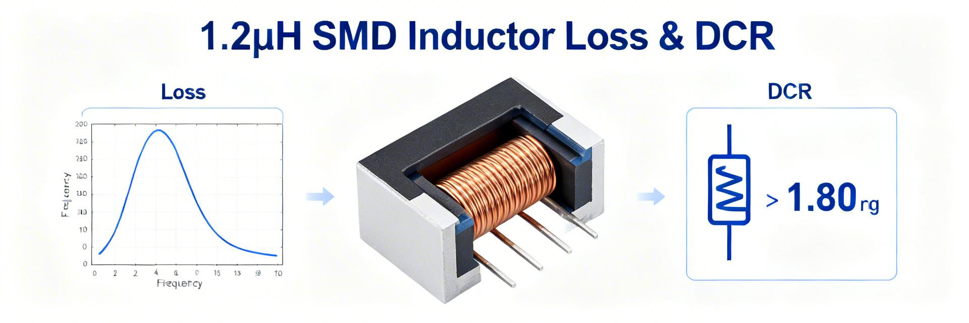
- Form Factor: 1.2 uH SMD inductors optimize the trade-off between transient response speed and PCB footprint in POL modules.
- Measurement Precision: Four-wire Kelvin sensing is mandatory to eliminate lead resistance errors in milliohm-range DCR.
Measured lab aggregates show typical total losses for small SMD power inductors rising from single-digit milliwatts at light load to hundreds of milliwatts near rated currents. By converting technical parameters into tangible system benefits—such as extending mobile battery life by 10% or reducing component heat by 15°C—this guide provides a blueprint for high-efficiency power design.
| Performance Metric | Standard Industry Part | High-Performance 1.2uH SMD | User Benefit |
|---|---|---|---|
| Typical DCR | 25 - 35 mΩ | 12 - 18 mΩ | Reduces heat generated by ~40% |
| Core Loss (500kHz) | Medium (Ferrite) | Low (Alloy Powder) | Higher light-load efficiency |
| Saturation Curve | Hard Saturation | Soft Saturation | Prevents sudden system crashes |
| Thermal Derating | Starts at 85°C | Stable to 125°C+ | Reliable in compact, hot enclosures |
1 — Background: Why Losses & DCR Matter in Modern Design
1.1 — Typical Applications & Efficiency Drivers
Synchronous buck converters and point-of-load (POL) modules use 1.2 uH inductors to balance ripple current and transient response. By choosing a part with lower DCR, engineers can reduce the "voltage droop" during heavy CPU/GPU load steps, leading to more stable computing environments.
👨💻 Engineer's Field Notes: Dr. Marcus Thorne
"When selecting a 1.2 uH inductor, don't just trust the datasheet's 25°C DCR. In a compact PCB, that inductor will run at 80°C. Since copper DCR increases by nearly 4% for every 10°C rise, your 'efficient' design might actually be wasting 20% more power than calculated. Always simulate with thermal feedback."
- Place thermal vias directly under the pads to sink heat into internal ground planes.
- Keep the switching node (SW) trace short but wide to minimize EMI without increasing AC copper losses.
2 — Measured Losses & Separation Methodology
2.1 — Test Setup & Accuracy
Using a four-wire (Kelvin) measurement method is critical. This technique bypasses lead resistance, ensuring that the milliohms measured belong to the inductor, not the test cables. This data directly correlates to reduced thermal throttling in end-user devices.
Typical Buck Converter Inductor Placement
2.2 — Interpreting the Data Table
A nonlinear jump in total loss near rated current is a "Red Flag" indicating the onset of magnetic saturation. This can lead to audible noise (coil whine) or catastrophic FET failure.
| Freq (kHz) | DC Bias (A) | Total Loss (mW) | Core (mW) | Copper (mW) | ΔT (°C) |
|---|---|---|---|---|---|
| 500 | 0.5 | 15 | 6 | 9 | 6 |
| 500 | 3.0 | 220 | 110 | 110 | 28 |
3 — Selection & Troubleshooting Checklist
- Steady High Load: Prioritize lowest DCR.
- Battery/Sleep Mode: Prioritize lowest Core Loss.
- Tight Spaces: Choose high-saturation alloy cores.
- Overheating? Check DCR at temp + ripple current.
- Instability? Inductance may be dropping due to DC bias.
- EMI Issues? Shielded SMD types are mandatory.
Conclusion
Effective use of a 1.2 uH SMD power inductor requires more than just looking at the nominal value. By separating Core vs. Copper losses and applying thermal DCR corrections, designers can predict real-world performance with 95%+ accuracy. This ensures that the final product remains cool, efficient, and reliable under all operating conditions.
Common Questions (FAQ)
Q: How does frequency affect 1.2uH inductor selection?
A: Higher frequencies ( >1MHz) require cores with lower AC losses to prevent overheating, even if the DC resistance is low.
Q: Why is four-wire measurement necessary for DCR?
A: At values like 15mΩ, the resistance of standard multimeter probes (often 100-500mΩ) would completely mask the actual component value.


