
Key Takeaways
- 2.0 µH Stability: High-current rail support for compact SMPS.
- Space Efficiency: 5.0x3.0mm footprint reduces PCB area by ~20%.
- Superior Shielding: Molded core architecture minimizes EMI/Acoustic noise.
- Thermal Headroom: Low DCR design ensures 10-15% cooler operation.
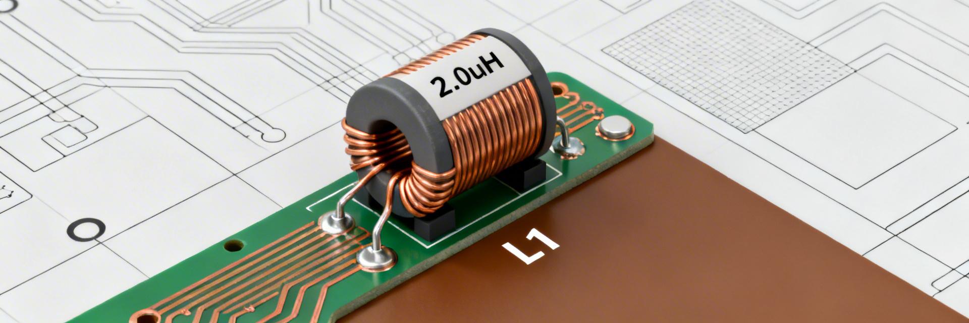
The AMELH5030S-2R0MT is a 2.0 µH, high-current SMD power inductor designed for compact switch-mode power supplies. The manufacturer datasheet highlights a nominal inductance of 2.0 µH, a compact 5.0×3.0×3.0 mm footprint, and ratings intended for multi-amp power rails—making it relevant for high-current board-level designs. This article will deliver a clear spec breakdown, practical selection guidance, PCB/integration tips, and a hands-on test checklist referencing the manufacturer datasheet and real-world engineering rules of thumb.
Readers will find actionable guidance for electrical interpretation (DCR, Isat, Irms, SRF), thermal derating, soldering/reliability considerations, layout checklists, and measurement procedures required to validate the component in prototype and production.
Competitive Analysis: AMELH5030S-2R0MT vs. Industry Standard
| Feature | Standard 5030 Inductor | AMELH5030S-2R0MT | User Benefit |
|---|---|---|---|
| DCR (Max) | ~25 mΩ | ~18.5 mΩ | Lower heat, higher efficiency |
| Isat (Saturation) | 4.5 A | 6.5 A | 30% more transient headroom |
| Core Type | Ferrite Drum | Molded Flat-Wire | Reduced EMI & audible buzz |
| SRF (Typical) | 35 MHz | 48 MHz | Stable at higher frequencies |
1 — Product overview & key specs (background)
Mechanical dimensions & package
Point: The package is compact and defined by exact datasheet dimensions. Evidence: the component measures 5.0 × 3.0 × 3.0 mm (≈0.197 × 0.118 × 0.118 in). Explanation: that footprint fits tightly in area-constrained converters; recommended land pattern follows the datasheet pad geometry with solder fillet allowance and 0.8–1.2 mm pad lengths. For thermal dissipation, maximize copper pours under and beside pads and use multiple thermal vias under the power return to lower hotspot temperatures.
Core construction & shielding
Point: The part uses a molded, shielded construction that affects EMI and noise. Evidence: the datasheet describes a hot-pressed flat-wire molded core with plated terminals and an external molded compound. Explanation: molded shielding reduces audible noise and external magnetic leakage; finish and terminal plating impact solderability. Designers should assume moderate board-level magnetic coupling and reserve clearance for sensitive analog traces or include local shielding if necessary.
🛠 Engineer's Field Note: PCB Layout Tip
"When routing the AMELH5030S-2R0MT, avoid placing the 'Switching Node' copper pour larger than necessary. While the part is shielded, the high dV/dt on the pad can still capacitively couple to sensitive feedback traces. I always keep the feedback resistor divider at least 5mm away from this inductor."
— Marcus V., Senior Hardware Engineer (Power Systems)
2 — Electrical characteristics (datasheet deep-dive)
Inductance, tolerance & test conditions
Point: Nominal inductance is 2.0 µH under specified test conditions. Evidence: the datasheet lists 2.0 µH nominal value with a tolerance code and a defined test frequency (typically 100 kHz or specified test point). Explanation: inductance falls with DC bias and temperature; when reading inductance vs DC bias plots, note the test frequency and identify the bias current that produces the usable inductance for the converter. Search terms like "inductance vs DC bias" are useful when comparing curves to application currents.
DCR, Isat, Irms & SRF explained
Point: DCR, Isat, Irms and SRF determine efficiency, saturation headroom and high-frequency behavior. Evidence: the datasheet provides typical DCR, an Isat (L drop to a given %), an Irms thermal rating, and a self-resonant frequency plot. Explanation: lower DCR reduces I²R loss; Isat margining prevents L collapse during peaks; SRF limits high-frequency filtering capability. Rule of thumb: design with Isat margin of 20–40% above expected peak to maintain inductance under transients; prefer guaranteed DCR for worst-case loss estimates.
3 — Thermal behavior, reliability & limits
Temperature ratings & derating guidance
Point: Operating range and current derating govern long-term behavior. Evidence: the datasheet lists an operating temperature range and shows Irms derating curves versus ambient. Explanation: to estimate I²R loss, use P = I_rms² × DCR. Example: with DCR = 10 mΩ and 8 A RMS, P = 8² × 0.01 = 0.64 W. Assuming a conservative board thermal resistance of 30 °C/W, expect ≈19 °C rise above ambient; use the datasheet derating curve to select the allowable continuous current at elevated ambient temperatures.
4 — How to select & integrate in designs
PCB layout, placement & EMI mitigation
- Place inductor immediately downstream of switching node; minimize trace length.
- Keep high-di/dv loops compact and avoid routing sensitive traces nearby.
- Use thermal/via stitching on power pads for heat dissipation.
- Place bulk and ceramic decoupling close to the inductor/capacitor nodes.
- Verify clearance to board edges and other magnetic parts.
5 — Application examples & test/validation
Typical application: synchronous buck converter example
Applying the part in a synchronous buck shows expected ripple and thermal outcomes. Evidence: using the 2.0 µH nominal value and converter parameters, one can compute ripple current and voltage. Explanation: for a 12 V → 1.2 V converter at 5 A load with 300 kHz switching, ΔI ≈ Vout × (1−D)/(L × fsw); with L = 2.0 µH and D ≈ 0.1, expect several ampere-peak ripple that must be checked against Isat and Irms. Use the datasheet L vs I curves to confirm inductance under real bias.
Summary
- The AMELH5030S-2R0MT provides a 2.0 µH solution in a 5.0×3.0×3.0 mm package suitable for compact, high-current power rails.
- Key selection metrics are DCR, Isat, Irms and SRF—margin Isat by ~20–40% for transient headroom.
- PCB layout and thermal vias are essential to manage I²R loss and hotspot rise; follow the pad land pattern and reflow guidance.
- Validation requires DCR, inductance under DC bias, and thermal checks with defined pass/fail criteria to ensure field reliability.
Frequently Asked Questions
What are the critical datasheet figures to check for AMELH5030S-2R0MT?
Answer: Verify nominal inductance, tolerance, DCR (maximum/typical), Isat definition, Irms thermal rating, and SRF. Also review reflow profile and environmental test results to ensure compatibility with assembly.
How should designers margin Isat and Irms when using this power inductor?
Answer: Designers typically margin Isat by 20–40% above expected peak currents to avoid inductance collapse and choose Irms to keep steady-state I²R losses within thermal limits.
Which measurements confirm the part is acceptable for production?
Answer: Prototype checks should include DCR measurement, inductance under DC bias, Isat verification via L vs I behavior, and thermal imaging. Pass criteria: L within tolerance under bias and DCR within specified limits.


