
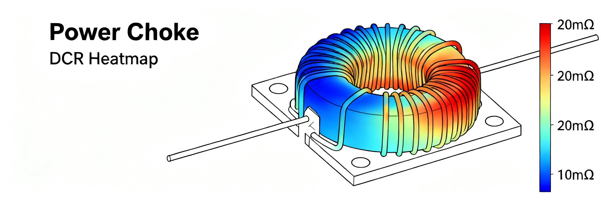
Point: Measured DCR for the AMELH5050S-R50MT family sits in the single-milliohm range and, combined with high RMS currents, produces significant copper loss and rapid temperature rise.
Evidence: typical winding resistance is on the order of 0.5–1.5 mΩ and I²R losses dominate at tens of amperes.
Explanation: designers must understand thermal limits and DCR to prevent drift, soft-saturation or reliability issues and to derive realistic derating and PCB rules.
Point: This document summarizes thermal behavior, shows loss calculations, and gives practical derating and layout rules.
Evidence: worked examples and bench-test recommendations are included for 10 A–40 A sweeps.
Explanation: following these steps yields conservative operating currents, robust layout guidance, and clear measurement methods for DCR and temperature dependence.
1 — Product overview & critical electrical specs (Background)
1.1 Key electrical parameters to summarize
Point: Critical electrical parameters are nominal inductance, tolerance, rated current, DCR, SRF, and soft-saturation behavior. Evidence: for a target variant, a representative one-row summary simplifies selection. Explanation: DCR directly sets copper loss; rated current and saturation knee determine usable current range under load and switching conditions.
| Parameter | Value (typical) | Notes |
|---|---|---|
| Inductance (nominal) | 50 µH | ±20% typical tolerance |
| DCR (typical) | 0.8 mΩ | single-milliohm range; measure at 25 °C |
| Rated current (saturation) | ~50 A (magnetic limit) | soft-saturation before hard knee |
| SRF | hundreds of kHz | AC behavior affects high-freq loss |
1.2 Mechanical & thermal package implications
Point: Package size, mounting and copper contact control thermal path and measured DCR. Evidence: a 5050-style power choke transfers heat through terminations to PCB copper and thermal vias. Explanation: larger copper contact area and thermal vias lower θJA; conversely narrow solder pads or long traces increase board-conduction resistance and inflate measured DCR and ΔT during tests.
2 — Thermal behavior & limit analysis (Data analysis)
2.1 Power loss and self-heating calculations
Point: Copper loss is the dominant self-heating term and is approximated by P_loss ≈ I_rms² × DCR (adjust for AC effects). Evidence: use I_rms = I_peak × sqrt(Duty) for pulsed waveforms; for example DC-equivalent losses at 10 A, 20 A, 30 A and 40 A with DCR = 0.8 mΩ follow below. Explanation: include skin and proximity effects for high switching frequencies that raise effective AC resistance.
20 A → P ≈ 0.32 W
30 A → P ≈ 0.72 W
40 A → P ≈ 1.28 W
* For a 50% duty square wave use I_rms = I_peak/√2; AC loss correction factors may increase these numbers above the DC estimate at high kHz switching.
2.2 Thermal resistance, temperature rise & derating curves
Point: Estimate temperature rise with ΔT = P_loss × θJA and derive a safe operating current for given ambient limits. Evidence: if θJA is estimated at 20 °C/W (board-dependent), a 1.28 W loss yields ΔT ≈ 26 °C; combined with 50 °C ambient that would exceed common limits. Explanation: plot temperature-rise vs. current to extract a derating curve (I_max vs ambient) that keeps component below target case or winding temperature (e.g., <125 °C). Use conservative θJA values if board thermal design is minimal.
3 — DCR measurement, variation & temperature dependence (Data analysis / Methods)
3.1 Accurate DCR measurement technique
Point: Four-wire (Kelvin) measurement at controlled 25 °C gives the most reliable DCR readings. Evidence: use milliohm meters or µΩ-resolution sources/meters, apply low test currents to avoid self-heating, and remove lead/fixture resistance via proper fixturing. Explanation: avoid two-wire readings and long fixture leads; perform multiple repeats and allow cooldown between higher-current tests to prevent measurement bias.
3.2 DCR vs. temperature and batch variation
Point: DCR increases with temperature according to the copper TCR; batch spread adds further margin. Evidence: use R_T = R_25 × [1 + α × (T − 25 °C)] with α ≈ 0.0039/°C for copper as an initial model. Explanation: a 50 °C rise increases DCR ~19% (1 + 0.0039×50), so include that in loss loops and add manufacturing tolerance (e.g., ±10–20%) when calculating worst-case losses and derating.
4 — Practical bench tests & example results (Case study)
4.1 Recommended bench test setup and test matrix
Point: Use a PCB footprint representative of the target layout, apply thermocouples on the winding/terminals and IR imaging in a controlled ambient. Evidence: run DC current sweeps from 0 A to 40 A in steps, recording DCR, part temperature, and inductance; also test switching at representative frequencies to capture AC losses. Explanation: this matrix isolates DC copper loss, temperature feedback, and any frequency-dependent losses so designers can map derating curves to actual board conditions.
4.2 Interpreting results and common failure modes
Point: Look for nonlinear temperature rise, increasing DCR or inductance collapse as signs of soft saturation or thermal runaway. Evidence: a steady upward DCR trend with increasing current indicates heating; sudden inductance drop at high DC bias signals soft saturation. Explanation: corrective choices include increasing copper area, adding thermal vias, paralleling inductors, or selecting a higher-saturation part to reduce per-part RMS current.
5 — Design guidelines & mitigation strategies (Action)
5.1 PCB layout, cooling and system-level mitigations
Point: Maximize copper area, use thermal vias under pads, and keep traces short and wide to reduce conduction losses. Evidence: thermal vias beneath the choke improve θJA dramatically; airflow and heatsinking further reduce ΔT. Explanation: when I_rms per part remains high, consider paralleling devices or selecting higher inductance/current parts to split losses and lower temperature per unit.
5.2 Derating rules and selection checklist
Point: Apply conservative derating and a selection checklist before committing to a part. Evidence: common rules are to operate at ≤60–70% of listed rated current in constrained thermal environments and to budget for DCR rise with temperature plus manufacturing spread. Explanation: checklist items: expected I_rms, allowable ΔT, measurement plan (Kelvin), required PCB copper and vias, and contingency for paralleling or alternate parts.
Summary
- AMELH5050S-R50MT designers must budget I²R losses using measured DCR and include temperature-dependent DCR increases when calculating thermal limits and derating curves.
- Accurate DCR measurement (Kelvin method at 25 °C) and conservative θJA estimates are essential to translate losses into temperature rise and safe operating current.
- PCB layout choices — copper area, thermal vias, short wide traces and airflow — directly reduce ΔT and expand usable RMS current margins.
Frequently Asked Questions
How should I measure DCR for AMELH5050S-R50MT to get repeatable results?
Use a four-wire Kelvin method with the part at controlled 25 °C, minimal test current to avoid heating, and a fixture that minimizes lead resistance. Record multiple readings after thermal stabilization and subtract any board trace contributions. Calibrate the instrument and allow cooldown between higher-current runs to ensure repeatability.
How do I convert measured DCR into a derating curve for thermal limits?
Compute P_loss = I_rms² × DCR, estimate θJA for your PCB, then ΔT = P_loss × θJA. For a chosen maximum winding or case temperature, solve for I_rms at various ambient temperatures to build an I_max vs ambient derating curve. Include DCR increase with temperature and manufacturing spread as safety margins.
When are AC effects important compared to DC DCR for thermal limits?
AC effects—skin and proximity losses—become significant when switching frequencies push current distribution into regions where effective resistance rises (usually high hundreds of kHz or above depending on geometry). If switching loss tests show power above DC I²R estimates, include measured AC loss factors or run frequency sweep tests to capture true thermal loading.


