
Point: The AMELH5050S-120MT is presented in the manufacturer datasheet with headline numbers that determine its suitability for power converters: nominal inductance, maximum DCR, Isat (saturation current), Irms (rated current), SRF and tolerance.
Evidence: those table entries form the primary pass/fail checks engineers use during component validation.
Explanation: this article gives a concise, testable breakdown of the AMELH5050S-120MT datasheet and practical lab steps to verify those inductor parameters in real designs.
(1/6) — Overview: What the AMELH5050S-120MT Is and Where It Fits
— Part identity & package basics
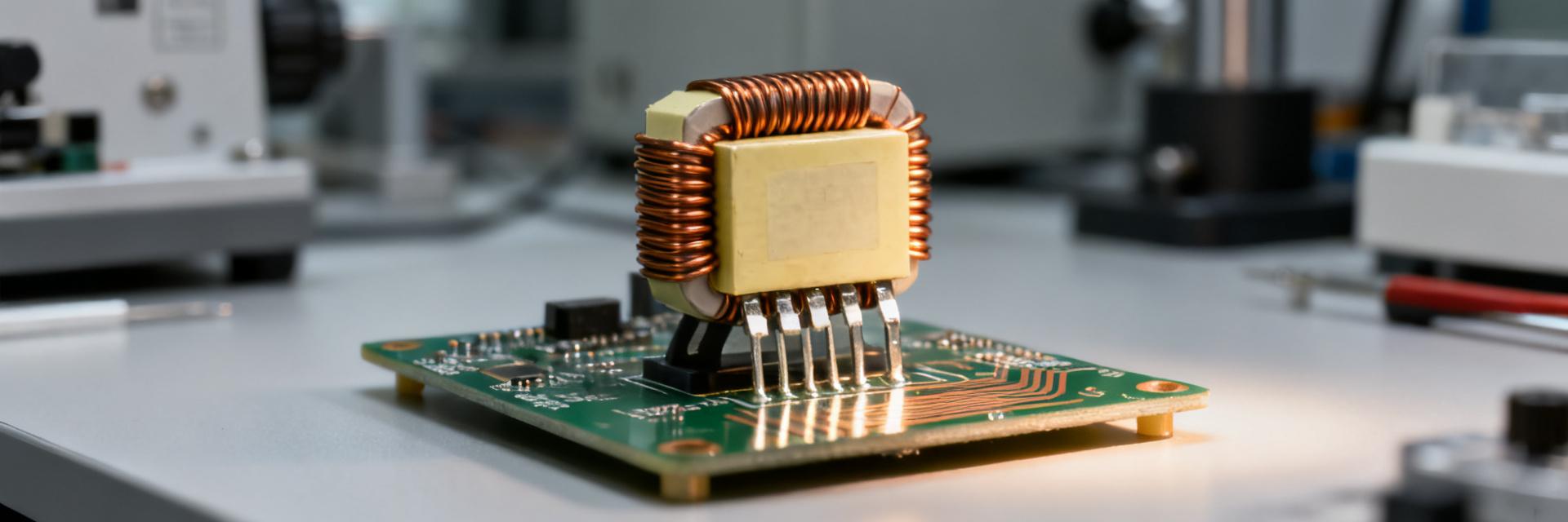
Point: The AMELH5050S-120MT is a shielded, molded SMD power inductor in a 5.0×5.0 mm footprint with low profile suitable for surface-mount power stages.
Evidence: the part name encodes series, package and value; the datasheet lists exact footprint and maximum height plus recommended land pattern.
Explanation: when reviewing the mechanical section, verify footprint dimensions, pad-to-pad clearance and manufacturer mechanical tolerances against your PCB fab drawings to avoid rework during assembly.
— Quick-spec snapshot
Point: For quick reference, extract the nominal inductance, tolerance, DCR (max), Isat (definition), Irms and SRF into a one-line spec used in design docs.
Evidence: the datasheet electrical table and “characteristics” rows show measurement conditions and limits.
Explanation: below is a recommended spec line you can copy directly into procurement and test plans.
| Parameter | Value (example from datasheet table) |
|---|---|
| Nominal inductance | 12 µH ±20% |
| DC resistance (max) | 0.085 Ω |
| Isat (L drop 30%) | 8 A |
| Irms (ΔT spec) | 5.5 A (≤40°C rise) |
| Self‑resonant frequency (SRF) | ~30 MHz |
| Operating temp | -40 °C to +125 °C |
Actionable: extract each number from the corresponding datasheet row—inductance from the “Inductance” column (test frequency noted), DCR from “DC Resistance,” Isat/Irms from “Current Rating” or “Saturation” rows—and convert units as needed.
(2/6) — Electrical Characteristics & Test Conditions
— Understanding inductance, frequency response, and measurement conditions
Point: Datasheet L values are frequency- and instrument-dependent; common test frequencies are 100 kHz or 1 MHz.
Evidence: the electrical table lists the L test frequency and instrument conditions (LCR bridge mode).
Explanation: reproduce the same test frequency and bridge settings (parallel/series mode) to match the datasheet. Expect L to fall slightly with frequency and with DC bias.
— Current ratings: Isat, Irms, and thermal derating
Point: Isat is typically defined as the DC current where inductance drops by a specified percentage (e.g., 20–30%); Irms is defined by a temperature-rise limit under AC loading.
Evidence: the datasheet will list Isat with the L-drop criterion and Irms with ΔT criteria.
Explanation: capture the L-drop percent and the ambient/fixture conditions to apply correct derating for higher ambient temperatures.
(3/6) — Losses & Impedance
Point: DCR sets I²R losses; Q and impedance vs frequency determine switching losses and ripple behavior.
Evidence: datasheet DCR and typical impedance curves guide loss estimates.
Explanation: measure DCR at room temperature and compute copper loss (Pcu = I²·DCR). Use inductor impedance at switching frequency to estimate AC/core-related losses.
(4/6) — Lab Verification
Point: A practical bench includes an LCR meter, 4‑wire DCR setup, programmable current source, and thermal probes.
Evidence: datasheet test methods assume precise measurement setups.
Explanation: use Kelvin connections for DCR, set LCR bridge on the datasheet test frequency, and monitor temperature with thermocouples during Irms testing.
(5/6) — Application Examples & PCB Integration Tips
Typical converter use-cases: The part is suitable for buck output filtering and DC input filtering where footprint and low EMI are priorities. Calculate ripple ΔI = Vout·(1−D)/(L·fsw) and choose an inductor value so peak current stays below Isat.
Layout Tips: Proper placement minimizes EMI. Keep it close to the switching node, minimize loop area, and size traces/vias for current. Use multiple thermal vias under heavy current traces to reduce heating.
(6/6) — Buying, Replacement & Sign-off
Pre-purchase checklist: Confirm L tolerance, DCR (max), Isat definition, Irms/thermal-rise details, SRF, and RoHS compliance. Use a one-line go/no-go: if any measured value is outside limits, hold procurement.
Selecting equivalents: When choosing alternates, match inductance and ensure DCR ≤ target and Isat with margin. Allow 20–30% current margin depending on the thermal environment.
Summary
- Confirm core electrical numbers (L, DCR, Isat, Irms) and reproduce exact datasheet test conditions in the lab.
- Run three key tests: L with DC bias, 4‑wire DCR + thermal‑rise, and an Isat sweep.
- Apply 20–30% current margin and verify PCB layout/thermal vias to manage losses.
常见问题解答 (FAQ)
How do I interpret AMELH5050S-120MT Isat on the datasheet?
Isat is usually given as the current at which inductance falls by a stated percentage (commonly 20–30%). To verify, perform an L vs DC current sweep, plot normalized L, and read the current corresponding to the datasheet’s L‑drop criterion.
What DCR tolerance should I expect for AMELH5050S-120MT in production?
Datasheets list a maximum DCR; production parts will vary below that max. Measure DCR with a 4‑wire method at room temperature and after thermal soak to characterize batch spread.
What lab proof tests should be logged before approving AMELH5050S-120MT for deployment?
Log and store: L vs frequency and L vs DC bias plots, 4‑wire DCR at 25 °C and elevated temperature, Isat sweep, SRF sweep, and a thermal‑rise test at rated Irms. Capture screenshots for traceability.


