AMELH6020S-R56MT Alternatives: Step-by-Step Power Rail Swap
Date:
2026-01-19 11:56:13
Source:
Browse:
0
Designers and repair engineers frequently face the pain of finding a drop-in or workable replacement when the AMELH6020S-R56MT is unavailable, obsolete, or thermally marginal. Choosing the wrong substitute can cause overheating, startup failures, or intermittent reverse-current issues that propagate through the rail.
The following practical, step-by-step workflow lays out how to inventory constraints, pick candidate classes, validate electrical and mechanical compatibility, and execute a controlled power rail swap. It includes clear alternative categories, measurable checks, and a validation checklist for a safe power rail swap and board revision.
Background: What the AMELH6020S-R56MT does and why swapping matters
— Core function and key specs to map (what to match)
Point: The device functions as a power-path/ideal-diode element with integrated MOSFET characteristics. Evidence: Key parameters to map include continuous and peak current ratings, on-resistance (Rds_on), package thermal resistance, gate charge, control thresholds, reverse-current blocking and soft-start behavior. Explanation: Any replacement must meet or exceed these values to preserve thermal margin, inrush control, and system protection in the same topology; mismatches often show as elevated junction temperature or unwanted bipolar conduction.
— Common swap scenarios and constraints
Point: Swaps typically arise from end-of-life parts, cost targets, or supply shortages. Evidence: Constraints include fixed PCB footprint, limited copper for thermal dissipation, and BOM cost ceilings. Explanation: Before selecting an alternative, inventory board constraints (pad layout, thermal vias, available airflow) and system constraints (allowed startup surge, acceptable voltage drop). This inventory narrows viable candidate classes quickly.
Alternative categories: quick comparison matrix
— Category A: PowerPath/ideal-diode controllers and integrated FETs
Point: Integrated power-path ICs combine control and MOSFET to simplify replacement. Evidence: Pros include predictable reverse-current blocking, built-in soft-start and compact footprints; cons are limited highest-current availability and sometimes higher cost per amp. Explanation: Use these power path IC alternatives when layout change must be minimal and system-level control features (load sharing, sequencing) are required.
— Category B: ORing controllers, analog switches, and discrete MOSFET solutions
Point: ORing controllers with discrete MOSFETs or analog switch solutions scale to higher currents and offer cost flexibility. Evidence: They require external gate drive components, careful thermal layout, and may introduce slower response or higher switching transients. Explanation: Choose discrete solutions for high-current rails or when Rds_on performance demands exceed integrated parts; plan for additional validation of inrush and transient suppression.
How to pick a direct replacement: decision checklist
— Electrical compatibility checklist (mandatory)
•
Voltage range: confirm Vmax and Vds margin ≥ 20% over worst-case peaks.
•
Current: continuous and short-term peak currents measured on the board; candidate must meet both.
•
Rds_on & thermal resistance: calculate power loss (I^2·Rds_on) and verify package thermal capability.
•
Gate charge and control thresholds: ensure timing and gate drive currents are compatible to avoid oscillation.
•
Reverse-current behavior and soft-start: verify presence or emulate with external components if missing.
— Mechanical and lifecycle checklist (practical)
Point: Mechanical fit and supply reliability are as critical as specs. Evidence: Check footprint/pad compatibility, thermal pad soldering needs, recommended reflow profile, RoHS, lead times, and lifecycle status. Explanation: If a candidate requires PCB rework, weigh redesign cost versus temporary adapter boards; maintain a supplier backup and mark parts in revision control to speed future swaps.
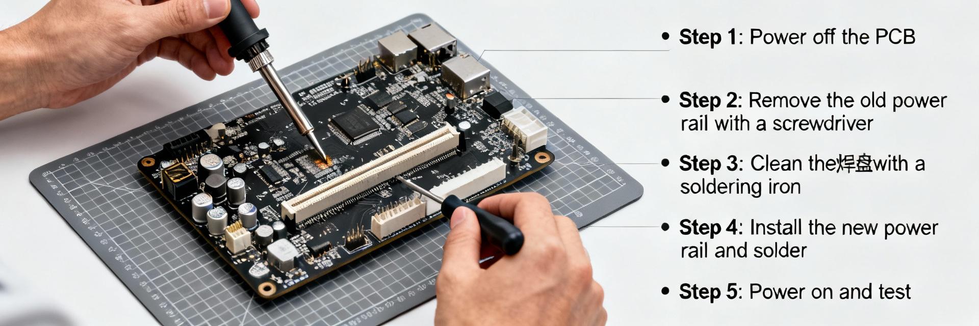
Step-by-step power rail swap procedure (practical guide)
— Preparation and safety steps (before soldering)
Point: Prepare a controlled bench plan. Evidence: Required items: ESD-safe workspace, soldering/reflow tools, current-limited PSU, breakout PCB or adapter, multimeter, oscilloscope, current probe, and thermal camera. Explanation: Review schematic and BOM, order multiple candidate parts, create a simple test jig reflecting the board's parasitics, and document planned test vectors in version control before any assembly.
— Swap execution, testing and validation (step-by-step)
•
Bench-test candidate on breakout: confirm pin mapping, Vgs thresholds, and leakage under single-rail conditions using a current-limited supply and scope to capture switching behavior.
•
Populate on board: use controlled reflow or fine-tip soldering, then power up with current limit; observe startup waveform and soft-start behavior.
•
Monitor run-time metrics: measure steady-state voltages, temperature rise with thermal camera, inrush with current probe, and transient response with scope under representative loads.
•
Regression and stress tests: run functional tests, EMI spot checks if switching changes, and a burn-in at elevated temperature to expose marginal thermal or stability issues.
For each step, log multimeter readings, scope captures, thermal images, and pass/fail criteria so swaps are reproducible and auditable.
Case examples & common pitfalls (practical case-study style)
— Example swap scenarios (concise vignettes)
Point: Two concise examples illustrate trade-offs. Evidence: Example A—low-current audio rail replaced with an integrated power-path IC for compactness; result: reduced dropout and simplified layout. Example B—high-current motor supply needed discrete MOSFETs for lower Rds_on; result: required layout changes and improved thermal performance. Explanation: Cases show that selection depends on current scale and acceptable PCB changes.
— Troubleshooting common failure modes
Point: Common failures include overheating, inrush-triggered PSU trips, oscillation, and ringing. Evidence: Detection via thermal camera, scope (ringing/transients), and sudden voltage sag under load. Explanation: Quick fixes include adding snubbers, increasing gate resistance, soft-start adjustments, or improving thermal vias; persistent issues often require layout or component-class changes.
Final checklist & rollout recommendations
— Pre-release checklist for production
✓
BOM sign-off with alternate suppliers and lead-time verification.
✓
Test coverage: functional, thermal, EMI, and regression passed.
✓
Assembly notes: reflow profile, placement tolerances, and handling precautions.
✓
Supplier backup plan and parts-obsolescence tracking.
— Field support and revision control
Point: Documenting and communicating the change prevents costly field issues. Evidence: Update schematics, BOM, test procedures, and firmware version tags; notify manufacturing and service teams. Explanation: Maintain a parts-obsolescence plan and log bench-validation artifacts so future engineers can reproduce the decision rationale quickly.
Summary
In short, the structured approach above empowers engineers to evaluate AMELH6020S-R56MT alternatives methodically and execute a verifiable power rail swap using the provided step-by-step workflow. Prioritize electrical compatibility, mechanical fit, and lifecycle robustness while recording objective test data throughout the swap.
•
Map electrical specs first: voltage, continuous and peak current, Rds_on, and reverse-current behavior before selecting a class of alternatives.
•
Use integrated power-path parts for compactness; opt for discrete MOSFETs for best thermal/current performance and accept layout changes when needed.
•
Follow a staged validation: breakout bench tests, controlled board-level power-up, instrumentation capture, and burn-in to confirm reliability.
Common Questions
— How to verify a candidate for a power rail swap?
Conduct a bench verification on a breakout: check pin mapping, gate thresholds, leakage, and switching with a current-limited supply. Capture startup and transient waveforms with an oscilloscope and measure temperature rise under expected continuous load with a thermal camera. These objective checks predict in-system behavior before board population.
— When should a designer redesign the PCB instead of swapping parts?
If the replacement requires a different thermal pad, significantly different pinout, or additional high-current copper, redesign is usually warranted. Also redesign when long-term supply or lifecycle risks make temporary fixes risky; short-term adapters are OK for quick repairs but not for production sustainment.
— What instruments are essential during the step-by-step swap?
Minimum instruments: ESD-safe bench, current-limited DC supply, digital multimeter, oscilloscope with a proper probe, current probe for inrush, and a thermal camera or IR thermometer. These allow verification of voltages, transient behavior, current profiles, and thermal performance at each validation stage.
Quick visual: Vds margin target
Target: Vds margin ≥ 20% (visualized as the filled portion above).