
A data-driven analysis for modern high-current DC–DC converters, emphasizing low DCR and high saturation performance. This evaluation translates datasheet values into actionable design decisions for 20–30 A synchronous buck converters.
Part Overview & Baseline Background
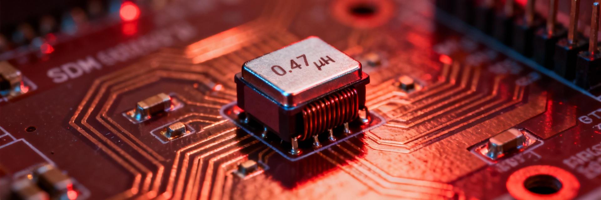
Package & Mechanical Dimensions
The AMELH6020S-R47MT utilizes a compact 6.0 × 2.0 mm SMD footprint, engineered for extreme current density. The design balances copper area for DCR reduction with solder fillet reliability. Engineers should implement 4–6 vias under the pad area for optimal thermal relief.
Electrical Specifications & Data Analysis
Current Ratings (Amperes)
DCR Tolerance (mΩ)
Measurement Procedures & Bench Setup
Accurate characterization requires a high-precision setup to avoid measurement artifacts in sub-milliohm DCR and high-frequency inductance values.
- LCR Meter: Capability for 100 kHz and 1 MHz sweeps.
- Current Source: DC bias supply up to 50 A.
- Kelvin Fixture: 4-wire milliohmmeter for DCR accuracy.
- Thermal Monitoring: IR camera or calibrated chamber.
20–30 A Synchronous Buck Evaluation
Using Vin = 12 V, Vout = 1 V, and fs = 500 kHz:
1. Duty Cycle (D) ≈ 0.0833
2. Ripple Current (ΔI) ≈ 3.9 A
3. Conduction Loss (P) ≈ I_DC² · DCR
Design Margin Recommendation: Operate at ≤70% of Isat to prevent saturation during transients.
Layout & EMI Mitigation
- Proximity: Place inductor immediately adjacent to switching nodes.
- Thermal: Maximize copper volume under the part for passive heat sinking.
- EMI: Maintain tight loop areas and consider snubber networks for high di/dt.


