
AMELH6020S-R20MT at a Glance
Point: Key device parameters determine test strategy.
Evidence: A shielded 60×20 mm high-current inductor with low DCR means measured drop is milliohms and sensitive to lead resistance and temperature.
Explanation: Shielding reduces stray fields but does not change DC resistance — use four-wire connections and thermal monitoring to capture true DCR and account for lot-to-lot tolerance per the datasheet.
Why Accurate DCR & Isat Measurements Matter
Point: DCR and Isat drive loss, thermal rise, and margin.
Evidence: Copper loss equals P = I² × DCR; a 10% DCR error at 30 A changes calculated loss by several watts and shifts thermal design.
Explanation: Accurate DCR yields correct I²R loss; correct Isat characterization ensures the design keeps inductance above required values under load and provides appropriate safety margin for reliability.
Interpreting Measurement Results
Converting DCR to Practical Metrics
Translate milliohm readings into watts at operating current. Use the copper temperature coefficient (≈ +0.393%/°C) for accuracy.
R_meas = 1.7 mΩ @ 30A
P = 30² × 0.0017 = 1.53 W
Understanding Isat vs Rated Current
Isat is defined where inductance falls by 10–30%. Maintain a 20–30% design margin between continuous current and Isat to prevent saturation during transients.
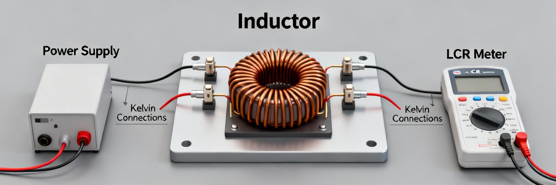
Measuring Low DCR — Tools, Wiring & Procedure
Recommended Tools & Fixture Tips
- Four-wire Kelvin milliohm meter or precision current source.
- Short heavy-gauge wiring to minimize parasitic resistance.
- Low-thermal alloy contacts to prevent EMF offsets.
- Secure bench fixture to prevent contact variation.
Step-by-Step Kelvin DCR Measurement
- Apply DC test current (1–5 A recommended for optimal SNR).
- Separate Force and Sense leads entirely.
- Allow thermal settling for 10–30 seconds.
- Average multiple readings and log ambient temperature.
Measuring Isat and Saturation Behavior
Example Measurement Walkthrough
Quick Pre-test Checklist
- Verify instrument calibration certificates.
- Zero the Kelvin fixture with shorting bar.
- Confirm Force/Sense wiring isolation.
- Check fusing and safety interlocks.
- Set up ambient temperature logging.
Common Errors & Fixes
Error: High thermal drift.
Fix: Allow part to reach equilibrium; use lower test current.
Error: Unstable milliohm readings.
Fix: Increase instrument averaging (NPLC) and check contact pressure.
Summary & Key Takeaways
Reliable measurement of DCR and Isat depends on four-wire techniques, temperature control, and controlled current ramps. Follow these procedures to produce traceable data for thermal and EMC design closure.
- Use Kelvin method for low DCR.
- Correct for temperature coefficients.
- Track L(I) curves for Isat.
- Apply 20-30% design margin.


