AMELH6060S-150MT: DCR & Current Ratings Deep Dive Now
The AMELH6060S-150MT lists a maximum DCR ≈ 30.8 mΩ and a saturation current around 7 A with a rated current near 7.5 A, figures that directly determine conduction loss, thermal rise, and usable headroom in point-of-load converters. This article explains what those DCR and current ratings mean in practice, how to measure and apply them, and how to verify the part in real designs.
Data-driven decisions matter: engineers must convert the published numbers into expected I²R loss, ΔT on the PCB, and safety margin under transient events. The guidance below prioritizes practical bench tests, conservative derating, and the critical spec items to confirm before procurement.
Background — Why this inductor code matters for modern power delivery
Role of low-DCR inductors in buck converters
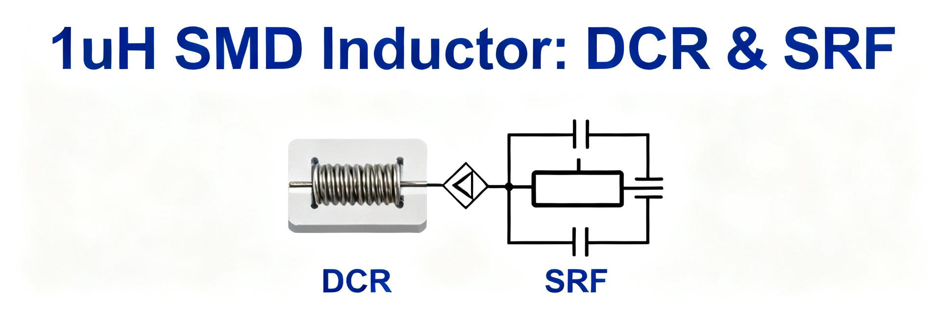
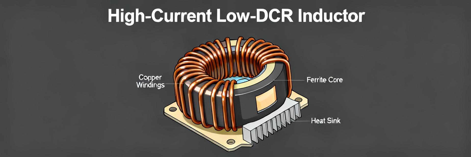
Point: Low DCR reduces I²R loss and improves converter efficiency. Evidence: I²R loss = I_rms² × DCR; voltage drop = I_rms × DCR. Explanation: For a given ripple and duty cycle, DCR directly converts RMS current into watts lost as heat; halving DCR roughly halves resistive loss. Designers targeting high efficiency prioritize DCR along with core loss metrics.
Interpreting manufacturer specs vs. real-world performance
Point: Published rated current and Isat are test-dependent. Evidence: Datasheet numbers reflect specific test conditions (temperature, waveform, measurement frequency). Explanation: Engineers should treat rated current as an application guideline and Isat as the point where inductance falls by a defined percentage; always read footnotes and confirm test current, ambient, and measurement method before relying on the spec.
Data Analysis — AMELH6060S-150MT: Electrical specs overview and spec interpretation
Key published numbers explained: DCR, rated current, saturation
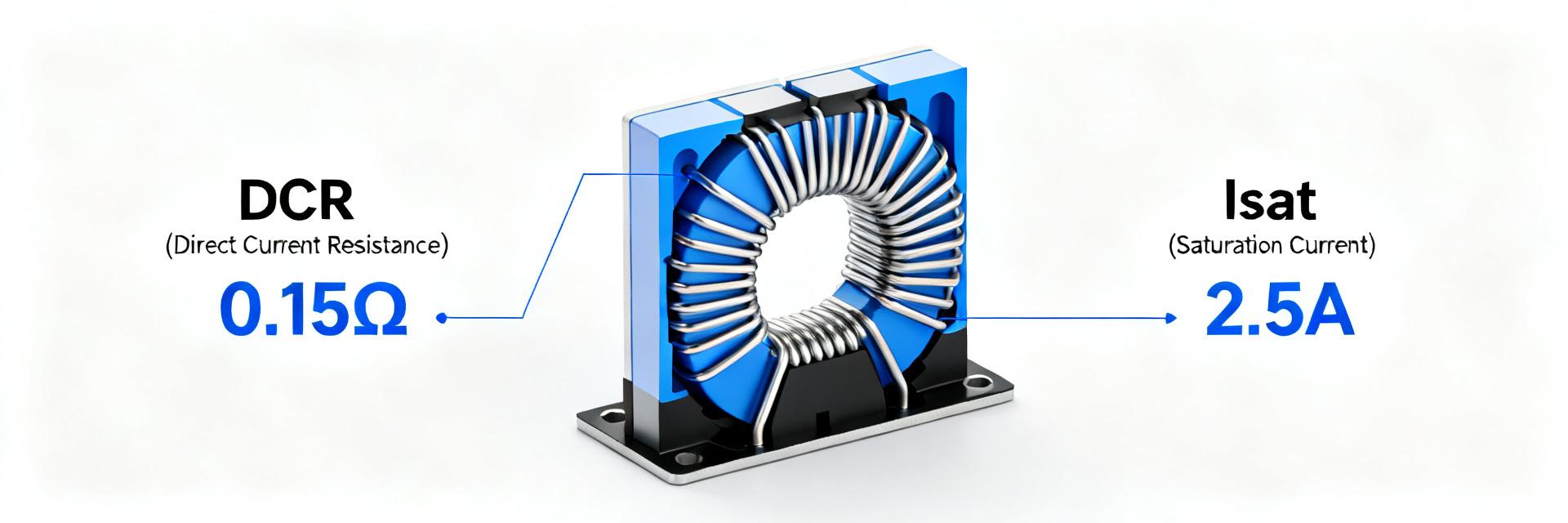
Point: Key numbers set electrical and thermal performance bounds. Evidence: Typical datasheet values: DCR max ≈ 30.8 mΩ, rated current ≈ 7.5 A, Isat ≈ 7 A. Explanation: "DCR max" is the worst-case series resistance affecting thermal worst-case; rated current is a recommended continuous limit; Isat is the current at which inductance has dropped by the manufacturer’s stated percent. Use DCR max for worst-case loss calculations and Isat to size transient headroom.
How to read the spec sheet: what’s missing and what to confirm
Point: Datasheets often omit usable details. Evidence: Common omissions include temperature coefficient, test frequency for impedance curves, and fixture method for DCR. Explanation: Before selection, confirm temp coefficient, measurement current for DCR, criteria used to define Isat, and whether impedance vs. frequency data are available. Checklist: confirm DCR test current, Isat definition, temperature range, and impedance curves.
Data Analysis — DCR behavior: temperature, frequency and manufacturing variance
DCR vs temperature: modeling and quick calculators
Point: Copper-based DCR increases with operating temperature. Evidence: Use R(T)=R25×[1+α×(T−25)], α≈0.00393/°C for copper. Explanation and example: Starting from 30.8 mΩ at 25°C, at 100°C the multiplier is 1+0.00393×75≈1.295, giving R≈30.8×1.295≈39.9 mΩ. That ~9.1 mΩ rise increases I²R loss proportionally and must be included in thermal budgets.
Frequency and AC effects: when DC resistance isn’t the whole story
Point: At switching frequencies, AC losses can exceed DC I²R loss. Evidence: Skin and proximity effects raise effective resistance; core losses add to the total loss at higher flux levels. Explanation: If the converter operates at high ripple frequency or with significant harmonic content, request impedance vs. frequency curves and core loss data. For many point-of-load designs the AC component can materially alter efficiency below or above the DCR-based estimate.
Methods / How-to — AMELH6060S-150MT: Recommended bench tests for DCR and current ratings
DCR measurement: setup, instruments, and repeatability tips
Point: Accurate DCR needs a Kelvin four-wire method. Evidence: Use a precision micro-ohmmeter or source-measure with four-wire fixture, apply a modest DC test current to avoid self-heating. Explanation: Clamp leads and fixture contact resistance cause error; average multiple measurements and use short test pulses or low current to prevent warming. Record ambient temperature for referenced comparisons against datasheet values.
Current / saturation testing: safe procedures and measurement points
Point: Isat testing requires controlled current ramps and inductance monitoring. Evidence: Ramp DC current while measuring inductance or the L(I) slope; identify the current where inductance drops by the manufacturer’s specified percentage. Explanation: Use thermal monitoring, keep ramps slow enough to avoid eddy heating, and stop before core or wire damage. Derive practical rated current by combining Isat margin with thermal limits and duty cycle.
Method / Application Guide — Selecting and applying the AMELH6060S-150MT in designs
Thermal management, PCB layout and derating rules
Point: Translate DCR and rated current into expected temperature rise. Evidence: Compute I²R loss (W) and allocate PCB copper area or heat spreader accordingly. Explanation: For continuous loads, adopt conservative derating—typical rule is 70–80% of rated current for continuous operation with limited cooling. Ensure wide, short traces, thermal vias under the part, and shared copper planes to keep junctions and ambient within safe limits.
Two concise design examples
Example A — 5 A buck: Point: estimate I_rms and I²R loss. Evidence: For 5 A DC with 20% ripple assume I_rms ≈ 5.1 A; I²R loss ≈ 5.1² × 0.0308 ≈ 0.803 W. Explanation: That loss reduces converter efficiency by roughly P_loss / P_out; for a 12 V→1.2 V, 5 A output, 0.8 W is a small but measurable hit and drives PCB thermal planning.
Example B — inrush-limited application: Point: verify saturation margin. Evidence: If expected peak transient is 9 A, but Isat ≈ 7 A, the part will exhibit inductance collapse. Explanation: Choose a part with Isat ≥ peak transient × safety factor (1.2–1.5) or add series limiting; confirm transient waveform and thermal dissipation during event before final selection.
Case + Action — Troubleshooting, failure modes, and replacement criteria
Signs DCR or saturation is causing problems
Point: Performance symptoms point to DCR/Isat issues. Evidence: Observe unexpected heating, efficiency loss, audible noise, or inductance drop under load. Explanation: Quick bench checks include Kelvin DCR measurement, inductance vs. DC bias sweep, and thermal imaging under realistic load. Correlate symptoms with measured deviations from datasheet values to isolate root cause.
Replacement and upgrade checklist
Point: Define objective replacement triggers. Evidence: Replace when measured DCR drifts beyond tolerance, visible thermal damage exists, or measured Isat no longer meets required margin. Explanation: When selecting alternates, tighten spec ranges: lower DCR, higher Isat, request impedance curves and temperature coefficient. Document verification tests for procurement and field replacement workflows.
Summary (action-oriented recap)
- AMELH6060S-150MT’s DCR (~30.8 mΩ) and current ratings (~7–7.5 A) set the baseline for conduction loss and usable headroom; always compute I²R loss and plan thermal mitigation accordingly.
- Verify datasheet test conditions: confirm DCR test current, Isat definition, and temperature coefficient before relying on rated current in a design.
- Perform Kelvin four-wire DCR checks and controlled Isat ramps in the lab; use conservative derating (70–80%) for continuous operation and a larger margin for transient-heavy applications.
FAQ
How should engineers interpret AMELH6060S-150MT DCR for thermal design?
Answer: Treat the listed DCR (use the max value) as the baseline for worst-case I²R loss and then adjust for operating temperature using R(T)=R25×[1+α×(T−25)]. Use the elevated resistance to compute steady-state power dissipation and size PCB copper or heat spreading to keep temperatures within safe limits.
What is the practical difference between rated current and saturation current for the AMELH6060S-150MT?
Answer: Rated current is a conservative continuous operating recommendation factoring thermal limits; saturation current (Isat) is the point where inductance falls by the manufacturer’s criterion under DC bias. Design margin requires both: ensure Isat exceeds peak transient current and rated current covers continuous RMS with derating.
Which bench tests provide the most reliable verification of current ratings?
Answer: Combine a four-wire Kelvin DCR measurement at reference temperature with an inductance vs. DC bias sweep to locate Isat. During Isat testing, ramp current slowly with thermal monitoring and record inductance collapse and temperature. These tests together validate both conduction loss and magnetic headroom for the application.