AMELH6060S-5R6MT Deep Specs & High-Current Data Overview
The AMELH6060S-5R6MT is rated for roughly 11.6 A saturation/DC current with about 11.7 mΩ DCR and 5.6 μH inductance — numbers that immediately define its suitability for >10 A power rails. These ratings matter because they set limits on I²R losses, thermal rise, and saturation margin in synchronous buck converters and point-of-load regulators. This article gives a concise technical deep-dive, PCB/thermal integration guidance, comparison alternatives, and a procurement/qualification checklist for engineers selecting a power inductor for high-current designs.
1 — Product snapshot & market fit (background)

Key specs at a glance
Essential electrical and mechanical parameters to note: inductance 5.6 μH (test at 100 kHz), test frequency 100 kHz, Isat ≈ 11.6 A, Irms/ΔT rating for continuous current, DCR ≈ 11.7 mΩ, operating voltage 40 V, temperature range −40°C to +125°C, package footprint roughly 6.8 × 6.6 mm. Engineers should confirm measurement conditions (test current, temperature) when comparing parts and plan for derating in real systems.
| Spec | Value | Unit | Condition |
|---|---|---|---|
| Inductance | 5.6 | μH | 100 kHz |
| Isat | ≈11.6 | A | specified saturation |
| DCR | ≈11.7 | mΩ | room temp |
| Package | 6.8 × 6.6 | mm | top view |
Typical applications & where it fits vs. other power inductors
This part targets synchronous buck converters, POL regulators, battery rails, automotive infotainment, and server VRMs where sustained currents exceed 10 A. It balances ripple handling and low DCR in a compact 6.8×6.6 mm footprint. Compared with smaller 4×4 options the 6060 format offers higher current capability at modest area cost; versus 8×8 formats it trades slightly higher DCR for smaller board area and cost savings.
2 — Electrical performance & real-world data analysis (data analysis)
DC current, saturation, DCR and practical implications
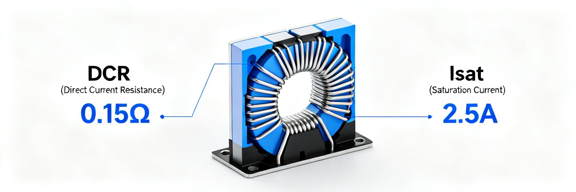
Isat indicates the DC current at which inductance drops by a specified percentage; Irms/ΔT defines allowable continuous current for a temperature rise. Use I²·DCR to estimate winding losses: at 10 A, loss = 10² × 0.0117 Ω ≈ 1.17 W. That heat must be removed by PCB copper and vias; derate Isat/Irms for ambient temperature, continuous duty, and ripple — common practice is 10–20% derating for continuous thermal margin.
Frequency response, SRF & AC behavior
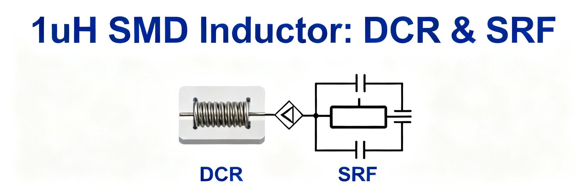
Inductance is specified at 100 kHz but switching converters commonly run 300 kHz–2 MHz. Inductance can drop with DC bias and frequency; confirm impedance vs. frequency and phase to model ripple and EMI. Self-resonant frequency (SRF) for similar 6060 variants often sits well above switching bands (tens of MHz), but validate SRF when designing snubbers or wideband filters. Recommended tests: impedance sweep, phase, and L vs. DC bias using a calibrated fixture.
3 — PCB integration & thermal management (method guide)
Footprint, soldering & assembly considerations
Design a land pattern with generous copper pads and thermal relief to spread heat. Place multiple thermal vias under or beside pads (staggered) to transfer heat to internal planes; maintain stencil apertures to avoid tombstoning and ensure proper solder fillets. Follow standard reflow profiles for lead-free assembly and verify pick-and-place orientation; inspect coplanarity and visible fillet for solder reliability.
Thermal management, cooling and derating strategies
Primary thermal path is conduction into PCB copper and vias. Rule-of-thumb: increase copper area and via count proportionally with continuous current — e.g., double copper pour area or add 6–10 vias to reduce ΔT for every additional few amps. Measure temperature rise at steady state (ambient controlled) and correlate to Irms specification. Reduce DCR heating and EMI by using wider traces, parallel power planes, and keeping the inductor away from heat-sensitive ICs.
4 — Application examples & alternatives (case study)
Two quick application scenarios with numbers
Scenario A — 12 V → 1.2 V at 12 A (synchronous buck). Estimated ripple current depends on switching frequency and chosen inductance; with 5.6 μH at 500 kHz, ΔI ≈ Vout·(1−D)/(L·fsw) gives modest ripple but larger L increases transient response time. I²R loss at 10–12 A is ~1.17–1.68 W; thermal planning must support that. Verify temperatures and ripple in prototype.
Scenario B — POL on server board with transient 0→12 A spikes. Prioritize saturation margin and low DCR to minimize voltage droop during transients; tighter layout and multiple parallel planes help. Validate transient response with step-load testing and monitor inductor temperature under repetitive pulses.
Comparable parts & trade-offs
Selection criteria matrix should include: current capability, DCR, size, SRF, cost, availability. Example row: AMELH6060S-5R6MT — current: ~11.6 A, DCR: ~11.7 mΩ, size: 6.8×6.6 mm, SRF: high, cost: moderate. Competitors may offer lower DCR at larger footprint or higher cost; choose based on thermal budget, board area, and unit cost targets.
| Part | Current | DCR | Size | Trade-off |
|---|---|---|---|---|
| AMELH6060S-5R6MT | ~11.6 A | ~11.7 mΩ | 6.8×6.6 mm | Compact, modest DCR |
5 — Procurement, testing & content/SEO guidance (action checklist)
Qualification & test checklist before production
Incoming inspection: visual, dimensional check. Electrical validation: DCR at room temp, L at test frequency, IRMS temperature-rise test under representative cooling. Mechanical: solderability and reflow performance. Reliability: thermal cycling and sample life test at rated temp/current. Suggested acceptance: mean DCR within spec ±10%, temperature rise within datasheet ΔT at rated Irms for sample lot; sample sizes depend on risk (pilot run 30–50 pcs).
Procurement tips, stock & SEO/copy guidance for writers
Procurement: check reel packaging, MOQ, and lead-time variability; use vendor traceability and anti-counterfeit checks. For technical content, include the main keyword sparingly and focus on measurement-based claims, test templates, and actionable PCB/thermal guidance. Meta suggestion: concise description under 160 characters highlighting rated current, inductance, and purpose for quick discovery.
Summary
- AMELH6060S-5R6MT offers a compact 6.8×6.6 mm solution with ~11.6 A capability and low DCR suitable for >10 A rails; validate I²R losses and ΔT in prototypes.
- Design for thermal conduction: copper pours and vias reduce temperature rise and enable closer-to-rated continuous current.
- Run the listed electrical and thermal checks, compare alternatives with the matrix, and complete the procurement/qualification checklist before production.
Frequently Asked Questions
How should engineers derate AMELH6060S-5R6MT for continuous operation?
Derate by 10–20% from peak Isat/Irms for continuous ambient and elevated temperatures: consider the DUT’s steady-state temperature rise, add copper area or vias where needed, and verify with a controlled thermal test at target current. Use conservative margins when cooling is limited or when pulsed currents are frequent.
What test measurements are essential to validate a power inductor?
Essential tests: DC resistance at room temperature, inductance vs. frequency and DC bias, impedance vs. frequency (to find SRF), and thermal rise under representative current. In-system tests should include efficiency, ripple, and transient response on the intended PCB to capture real-world interactions.
Which PCB layout practices minimize inductor heating and EMI?
Use wide short traces on both input and output, maximize copper area under and around the inductor, add multiple thermal vias to inner planes, keep switching nodes short, and separate noisy nodes from sensitive analog ground. Parallel power planes and careful component placement reduce loop area and improve both thermal and EMI performance.