AMELH6020S-5R6MT: Current Performance & Specs Deep Dive
The AMELH6020S-5R6MT shows a nominal inductance of 5.6 µH with a form factor and thermal performance aimed at multi-amp DC‑DC converters; measured conduction loss improvements versus comparable wound inductors often exceed a few percent in typical buck rails. This article provides an actionable, measurement-focused breakdown of AMELH6020S-5R6MT specs, real-world performance expectations, reproducible test methods, and selection guidance targeted at power-design engineers tasked with prototype validation and production readiness.
AMELH6020S-5R6MT — Quick Specs & What to Look For
Designers should first confirm the part’s electrical envelope and mechanical constraints before layout or thermal modeling. The table below captures the core datasheet fields to extract; these drive loss calculations, saturation margins, and PCB footprint decisions.
Datasheet summary (required fields)
| Parameter | Typical / Nominal |
|---|---|
| Inductance (L) | 5.6 µH nominal |
| Tolerance | ±20% (typical — verify specific lot) |
| Rated current (Irms) | ~6–10 A (refer to datasheet for exact Irms) |
| Saturation current (Isat) | ~12–20 A (L drops to specified %) |
| DC resistance (DCR) | single-digit mΩ to low double-digit mΩ (datasheet value) |
| Max temperature | Typically 155 °C (component limit) |
| Self-resonant frequency (SRF) | Single-digit to low‑tens of MHz (application dependent) |
| Package / footprint | 6020-style flat-wire molded package; check recommended land pattern |
Nonstandard / package & footprint notes
Inspect package markings and the recommended PCB land pattern carefully: flat‑wire molded parts can have asymmetric terminal pads and expect specific pad lengths for reliable solder fillets. Common pitfalls include thermal via placement directly beneath the part changing solder volume (affecting measured DCR) and overly large solder fillets that alter contact resistance. Follow the manufacturer’s recommended footprint and avoid compressing the component with excessive stencil openings.
AMELH6020S-5R6MT Performance Analysis
Engineers assessing inductor performance should combine datasheet curves with bench validation to quantify the AMELH6020S-5R6MT behavior across DC and AC conditions. The discussion below provides interpretation guidance and sample calculations for conduction and magnetic limits.
DC performance: DCR, I-Rating & saturation
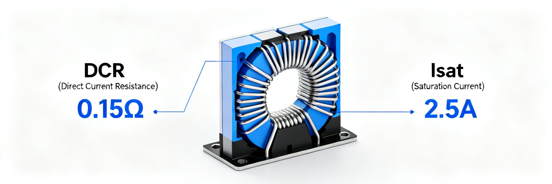
Point: DCR sets conduction loss; saturation limits usable current. Evidence: use the datasheet DCR and Isat curves. Explanation: estimate conduction loss with Pcond = I^2 × DCR (adjust DCR for temperature using the copper temperature coefficient). Example: at 8 A and DCR = 0.010 Ω, Pcond = 8^2 × 0.01 = 0.64 W. When selecting, compare this loss to switching losses to understand system efficiency impact. Read saturation curves to determine the current where L falls to 70–80% of nominal (soft vs hard saturation matters for converter control stability).
AC performance: impedance vs. frequency, SRF, and shielding effects
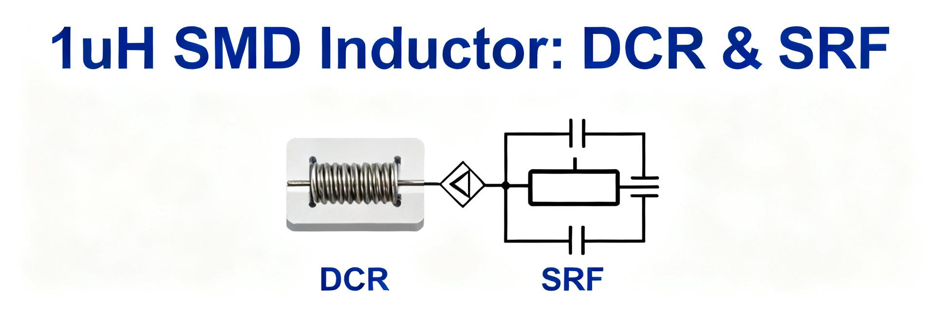
Point: The impedance curve dictates ripple attenuation. Evidence: datasheet Z(f) and L(f) plots or lab sweeps. Explanation: plot Z(f) to identify the frequency where inductive reactance dominates before SRF. Above SRF the part becomes capacitive; at switching frequencies approaching SRF, the inductor’s ability to filter ripple degrades. Shielding and core geometry affect distributed capacitance and EMI coupling—expect better EMI performance from shielded or molded flat‑wire designs compared with open‑wound parts.
Thermal, Saturation & Reliability Considerations
Translating electrical losses into thermal rise and lifetime requires conservative derating and practical mitigation steps. The following gives calculation templates and test recommendations.
Thermal modelling & derating
Point: I^2R losses produce temperature rise which shortens lifetime. Evidence: thermal resistance approximations and layout conductivity. Explanation: estimate temperature rise as ΔT ≈ Pcond × θJC_eff (θJC_eff is effective thermal resistance from component to PCB ambient). As a rule, derate continuous current to ~60–80% of Irated depending on cooling. Mitigation: increase copper pour, add thermal vias near current paths, and provide component spacing to reduce mutual heating.
Lifetime, inrush & transient behavior
Point: Inrush and transients can drive the part into saturation and thermal stress. Evidence: dynamic tests and accelerated cycling. Explanation: perform current‑ramp tests to observe inductance drop and core heating under surge. Recommended accelerated tests include multiple surge pulses at expected worst‑case currents, thermal cycling between operating extremes, and a defined pass/fail for inductance retention (for example,
How to Test, Measure & Integrate
Reproducible lab recipes reduce uncertainty when validating AMELH6020S-5R6MT in a given design. Below are stepwise measurement and layout recommendations.
Bench measurement recipes
- Measure DCR with a 4‑wire milliohm meter at ambient; record at 25 °C and estimate at operating temperature using copper temperature coefficient.
- Measure inductance at the intended switching frequency (e.g., 100 kHz) using an LCR meter; repeat at multiple frequencies up to expected SRF.
- Perform an impedance sweep (Z(f)) from 10 kHz to beyond SRF with a network or impedance analyzer; log L(f).
- For saturation: ramp DC current while measuring L; note the current where L drops to 70–80% of nominal. Use slow ramps and thermal stabilization between runs.
PCB integration & layout best practices
Place the inductor close to the switching node but ensure sufficient copper for heat spreading. Keep high‑current loop vias minimized and thick; place thermal vias outside the pad area as recommended. Recommended checks: verify actual pad copper weight, avoid routing high di/dt traces under the inductor body, and keep return paths short to minimize loop area for EMI.
Application Scenarios, Comparative Selection & Action Checklist
The AMELH6020S-5R6MT fits mid‑power buck regulators and point‑of‑load converters where a 5.6 µH inductance and robust current handling are needed. Below are fitment notes and a shortlist for pre‑production validation.
Ideal application cases & limitations
Best-fit: synchronous buck converters in the multi-amp range, post‑regulation for modules, and rails where moderate inductance and low profile are prioritized. Avoid when switching frequencies approach SRF or where the lowest possible DCR is mandatory (then consider larger or different‑core options). Expect modest efficiency gains when swapping from wound inductors due to reduced DCR.
Final selection & test-before-production checklist
- Confirm datasheet L, DCR, Isat, Irms, SRF, and package dimensions for selected lot.
- Bench test DCR (4‑wire), L at switching frequency, Z(f), and saturation current.
- Perform thermal derating simulation and prototype thermal run at expected load.
- Prototype in target PCB and verify EMI, temperature delta, and long‑term stability.
- Accept if DCR within tolerance, temperature rise within allowed delta, and L degradation
Key summary
- Confirm key datasheet numbers (5.6 µH nominal) and validate DCR/Isat in lab before layout finalization to ensure expected performance and efficiency.
- Use I^2R loss calculations and thermal modeling to set conservative derating (typically 60–80% of rated continuous current) and add copper/thermal vias as needed.
- Measure Z(f) to identify SRF and ensure switching frequency is well below SRF for reliable ripple filtering and EMI behavior.
Common Questions & Answers
What is the AMELH6020S-5R6MT DCR vs temperature behavior?
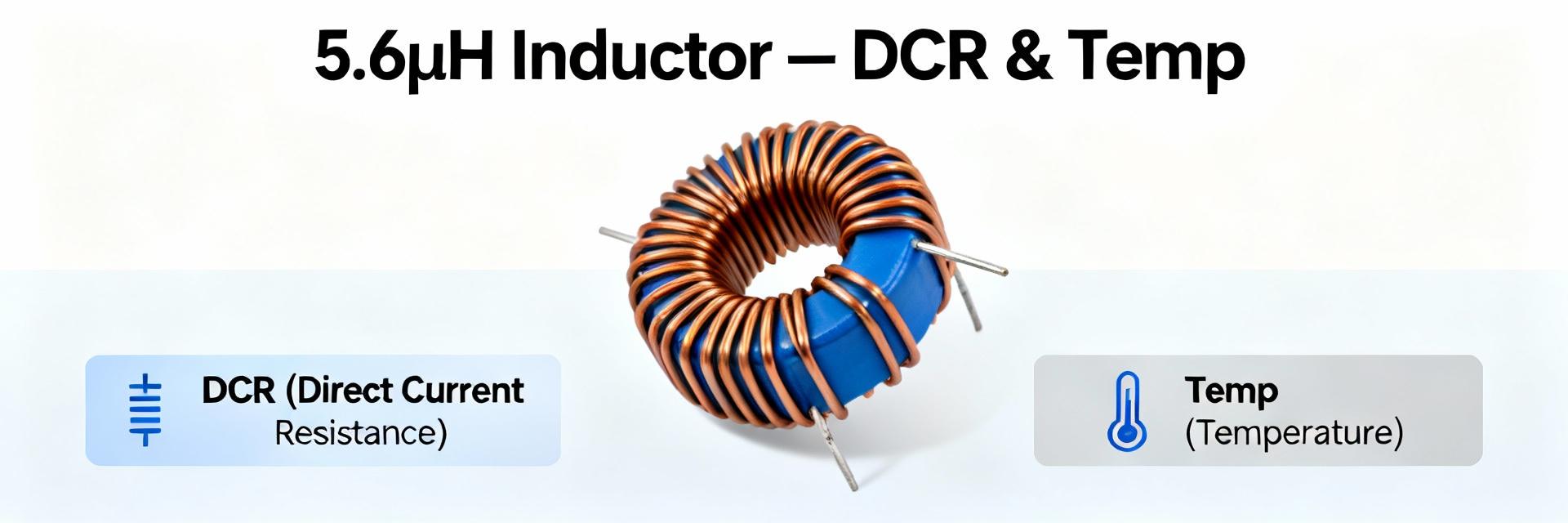
DCR increases with temperature approximately by copper’s temperature coefficient (~0.0039/°C). Measure DCR at known ambient, then apply ΔR ≈ R25 × α × ΔT to estimate operating DCR; validate with a temperature‑controlled test to capture assembly effects and solder joint contributions.
How to test AMELH6020S-5R6MT saturation current in the lab?
Ramp DC current through the inductor in small increments while measuring inductance with an LCR meter or impedance analyzer. Record the current where inductance falls to a predefined threshold (commonly 70–80% of nominal). Allow cooling between ramps to avoid thermal skew.
Which layout rules most affect AMELH6020S-5R6MT thermal performance?
Pad copper area, thermal via placement, and proximity of neighboring heat sources dominate thermal performance. Use large copper pours tied to the terminal pads, place thermal vias per manufacturer guidance, and avoid clustering hot components directly adjacent to the inductor.